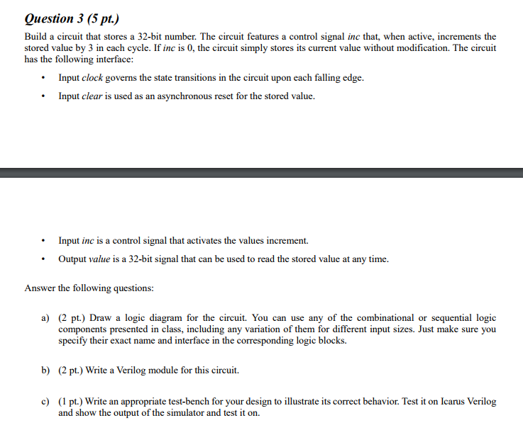
Question 3 (5 pt.) Build a circuit that stores a 32-bit number. The circuit features a control signal inc that, when active, increments the stored value by 3 in each cycle. If inc is 0, the circuit simply stores its current value without modification. The circuit has the following interface: Input clock governs the state transitions in the circuit upon each falling edge. Input clear is used as an asynchronous reset for the stored value. Input inc is a control signal that activates the values increment. Output value is a 32-bit signal that can be used to read the stored value at any time. Answer the following questions a) 2 pt) Draw a logic diagram for the circuit. You can use any of the combinational or sequential logic components presented in class, including any variation of them for different input sizes. Just make sure you specify their exact name and interface in the corresponding logic blocks. b) (2 pt.) Write a Verilog module for this circuit. c) (1 pt.) Write an appropriate test-bench for your design to illustrate its correct behavior. Test it on Icarus Verilog and show the output of the simulator and test it on Question 3 (5 pt.) Build a circuit that stores a 32-bit number. The circuit features a control signal inc that, when active, increments the stored value by 3 in each cycle. If inc is 0, the circuit simply stores its current value without modification. The circuit has the following interface: Input clock governs the state transitions in the circuit upon each falling edge. Input clear is used as an asynchronous reset for the stored value. Input inc is a control signal that activates the values increment. Output value is a 32-bit signal that can be used to read the stored value at any time. Answer the following questions a) 2 pt) Draw a logic diagram for the circuit. You can use any of the combinational or sequential logic components presented in class, including any variation of them for different input sizes. Just make sure you specify their exact name and interface in the corresponding logic blocks. b) (2 pt.) Write a Verilog module for this circuit. c) (1 pt.) Write an appropriate test-bench for your design to illustrate its correct behavior. Test it on Icarus Verilog and show the output of the simulator and test it on


