Answered step by step
Verified Expert Solution
Question
1 Approved Answer
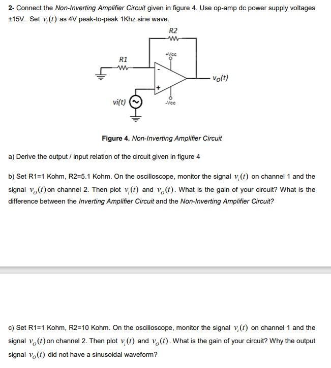
2- Connect the Non-Inverting Amplifier Circuit given in figure 4. Use op-amp dc power supply voltages +15V. Set v, (t) as 4V peak-to-peak 1Khz
2- Connect the Non-Inverting Amplifier Circuit given in figure 4. Use op-amp dc power supply voltages +15V. Set v, (t) as 4V peak-to-peak 1Khz sine wave. R1 ww vi(t) R2 www +Vcc -Vec vo(t) Figure 4. Non-Inverting Amplifier Circuit a) Derive the output / input relation of the circuit given in figure 4 b) Set R1=1 Kohm, R2=5.1 Kohm. On the oscilloscope, monitor the signal v (1) on channel 1 and the signal v (1) on channel 2. Then plot (1) and vo(1). What is the gain of your circuit? What is the difference between the Inverting Amplifier Circuit and the Non-Inverting Amplifier Circuit? c) Set R1=1 Kohm, R2=10 Kohm. On the oscilloscope, monitor the signal v(t) on channel 1 and the signal v (1) on channel 2. Then plot v(t) and vo(t). What is the gain of your circuit? Why the output signal vo(1) did not have a sinusoidal waveform?
Step by Step Solution
There are 3 Steps involved in it
Step: 1
a For the noninverting amplifier circuit given in Figure 4 VotVit 1 R2R1 b With R1 ...
Get Instant Access to Expert-Tailored Solutions
See step-by-step solutions with expert insights and AI powered tools for academic success
Step: 2

Step: 3

Ace Your Homework with AI
Get the answers you need in no time with our AI-driven, step-by-step assistance
Get Started


