

Answered step by step
Verified Expert Solution
Question
1 Approved Answer
QUESTIONS Q1. Two concentric cylindrical tubes placed inside each other are used as thin film reactor. The liquid climbing up between the two cylinders (annulus)
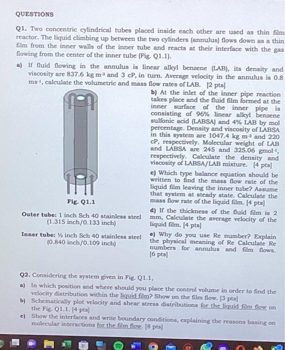
QUESTIONS Q1. Two concentric cylindrical tubes placed inside each other are used as thin film reactor. The liquid climbing up between the two cylinders (annulus) flows down as a thin film from the inner walls of the inner tube and reacts at their interface with the gas flowing from the center of the inner tube (Fig. Q1.1). a) If fluid flowing in the annulus is linear alkyl benzene (LAB), its density and viscosity are 837.6 kg m-3 and 3 cP, in turn. Average velocity in the annulus is 0.8 ms-1, calculate the volumetric and mass flow rates of LAB. [2 pts] Fig. Q1.1 Outer tube: 1 inch Sch 40 stainless steel (1.315 inch/0.133 inch) Inner tube: inch Sch 40 stainless steel (0.840 inch/0.109 inch) b) At the inlet of the inner pipe reaction takes place and the fluid film formed at the inner surface of the inner pipe is consisting of 96% linear alkyl benzene sulfonic acid (LABSA) and 4% LAB by mol percentage. Density and viscosity of LABSA in this system are 1047.4 kg m-3 and 220 cP, respectively. Molecular weight of LAB and LABSA are 245 and 325.06 gmol-, respectively. Calculate the density and viscosity of LABSA/LAB mixture. [4 pts] c) Which type balance equation should be written to find the mass flow rate of the liquid film leaving the inner tube? Assume that system at steady state. Calculate the mass flow rate of the liquid film. [4 pts] d) If the thickness of the fluid film is 2 mm, Calculate the average velocity of the liquid film. [4 pts] e) Why do you use Re number? Explain the physical meaning of Re Calculate Re numbers for annulus and film flows. [6 pts] Q2. Considering the system given in Fig. Q1.1, a) In which position and where should you place the control volume in order to find the velocity distribution within the liquid film? Show on the film flow. [3 pts] b) Schematically plot velocity and shear stress distributions for the liquid film flow on the Fig. Q1.1. [4 pts] c) Show the interfaces and write boundary conditions, explaining the reasons basing on molecular interactions for the film flow. [8 pts]
Step by Step Solution
There are 3 Steps involved in it
Step: 1

Get Instant Access to Expert-Tailored Solutions
See step-by-step solutions with expert insights and AI powered tools for academic success
Step: 2

Step: 3
Ace Your Homework with AI
Get the answers you need in no time with our AI-driven, step-by-step assistance
Get Started
Heat And Mass Transfer Fundamentals & Applications
Authors: Yunus A. Cengel, Afshin J. Ghajar
4th Edition
0073398128, 978-0073398129