Question
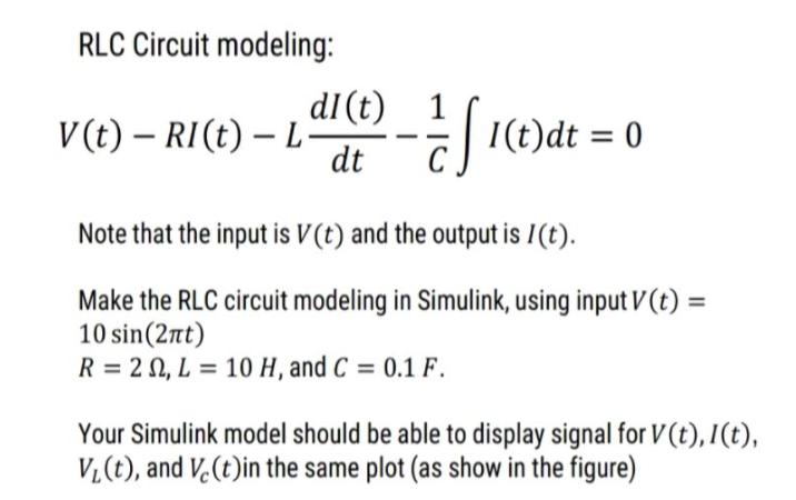
RLC Circuit modeling: dI(t) 1 V (t) RI(t) L EI(t)dt = 0 dt Note that the input is V(t) and the output is /(t).


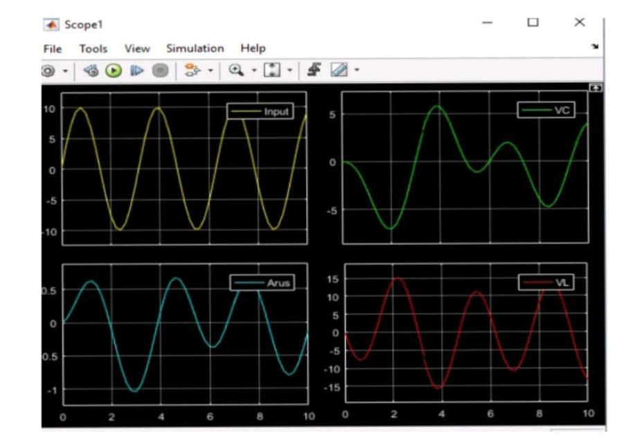
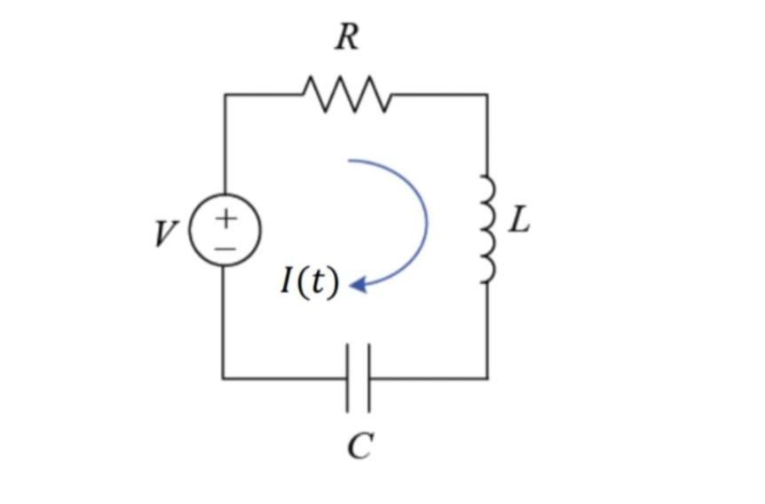
RLC Circuit modeling: dI(t) 1 V (t) RI(t) L" EI(t)dt = 0 dt Note that the input is V(t) and the output is /(t). Make the RLC circuit modeling in Simulink, using input V (t) = 10 sin(2nt) R = 2 0, L = 10 H, and C = 0.1 F. Your Simulink model should be able to display signal for V(t),I(t), V,(t), and V.(t)in the same plot (as show in the figure) Scopel File Tools View Simulation Help 10 -Input VC 5 10 15 Arus VL 0.5 10 5 -5 0.5 -10 -15 10 2 10 R + V L I(t) . C
Step by Step Solution
3.45 Rating (148 Votes )
There are 3 Steps involved in it
Step: 1
Series RLC M...
Get Instant Access to Expert-Tailored Solutions
See step-by-step solutions with expert insights and AI powered tools for academic success
Step: 2

Step: 3

Ace Your Homework with AI
Get the answers you need in no time with our AI-driven, step-by-step assistance
Get StartedRecommended Textbook for
Fundamentals Of Electric Circuits
Authors: Matthew Sadiku, Charles Alexander
3rd Edition
978-0073301150, 0073301159
Students also viewed these Electrical Engineering questions
Question
Answered: 1 week ago
Question
Answered: 1 week ago
Question
Answered: 1 week ago
Question
Answered: 1 week ago
Question
Answered: 1 week ago
Question
Answered: 1 week ago
Question
Answered: 1 week ago
Question
Answered: 1 week ago
Question
Answered: 1 week ago
Question
Answered: 1 week ago
Question
Answered: 1 week ago
Question
Answered: 1 week ago
Question
Answered: 1 week ago
Question
Answered: 1 week ago
Question
Answered: 1 week ago
Question
Answered: 1 week ago
Question
Answered: 1 week ago
Question
Answered: 1 week ago
View Answer in SolutionInn App


