Redo the ALU control logic incorporating the MIPS nor command. You should end up with a figures similar to figures D.2.1 through D.2.3.
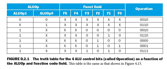
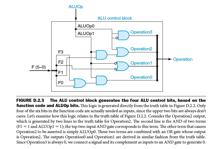
ALUOp Funct field Operation ALUOp1 ALUOp0 F5 F4 F3 F2 F1 FO 0010 0110 0010 0110 1 0 0 1 1 0 0 0 0001 1 0111 FIGURE D.2.1 The truth table for the 4 ALU control bits (called Operation) as a function of the ALUOp and function code field. This table is the same as that shown in Figure 4.13 ALUOp ALU control block ALUOp0 ALUOp1 Operation3 F3 F2 F1 F0 Operation2 Operation1 Operationo Operation F (5-0) FIGURE D.2.3 The ALU control block generates the four ALU control bits, based on the function code and ALUOp bits. This logic is generated directly from the truth table in Figure D.2.2. Only four of the six bits in the function code are actually needed as inputs, since the upper two bits are always don't cares. Let's examine how this logic relates to the truth table of Figure D.2.2. Consider the Operation2 output, which is generated by two lines in the truth table for Operation2. The second line is the AND of two terms (H = 1 and ALUOpl = 1 ); the top two-input AND gate corresponds to this term. The other term that causes Operation2 to be asserted is simply ALUOp0. These two terms are combined with an OR gate whose output is Operation2. The outputs Operation0 and Operationl are derived in similar fashion from the truth table Since Operation3 is always 0, we connect a signal and its complement as inputs to an AND gate to generate 0 ALUOp Funct field Operation ALUOp1 ALUOp0 F5 F4 F3 F2 F1 FO 0010 0110 0010 0110 1 0 0 1 1 0 0 0 0001 1 0111 FIGURE D.2.1 The truth table for the 4 ALU control bits (called Operation) as a function of the ALUOp and function code field. This table is the same as that shown in Figure 4.13 ALUOp ALU control block ALUOp0 ALUOp1 Operation3 F3 F2 F1 F0 Operation2 Operation1 Operationo Operation F (5-0) FIGURE D.2.3 The ALU control block generates the four ALU control bits, based on the function code and ALUOp bits. This logic is generated directly from the truth table in Figure D.2.2. Only four of the six bits in the function code are actually needed as inputs, since the upper two bits are always don't cares. Let's examine how this logic relates to the truth table of Figure D.2.2. Consider the Operation2 output, which is generated by two lines in the truth table for Operation2. The second line is the AND of two terms (H = 1 and ALUOpl = 1 ); the top two-input AND gate corresponds to this term. The other term that causes Operation2 to be asserted is simply ALUOp0. These two terms are combined with an OR gate whose output is Operation2. The outputs Operation0 and Operationl are derived in similar fashion from the truth table Since Operation3 is always 0, we connect a signal and its complement as inputs to an AND gate to generate 0