Answered step by step
Verified Expert Solution
Question
1 Approved Answer
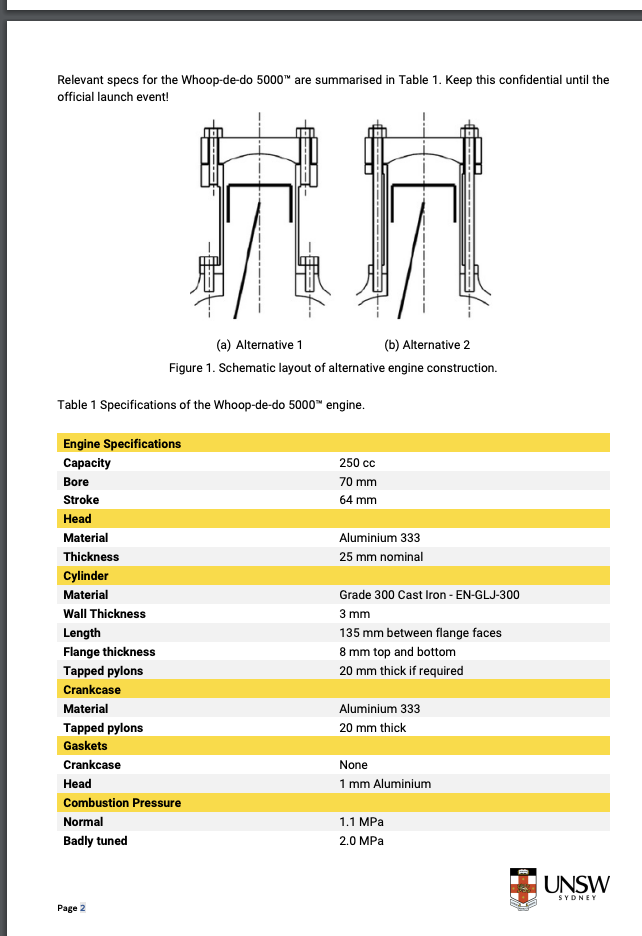
Relevant specs for the Whoop-de-do 5000 are summarised in Table 1. Keep this confidential until the official launch event! Table 1 Specifications of the


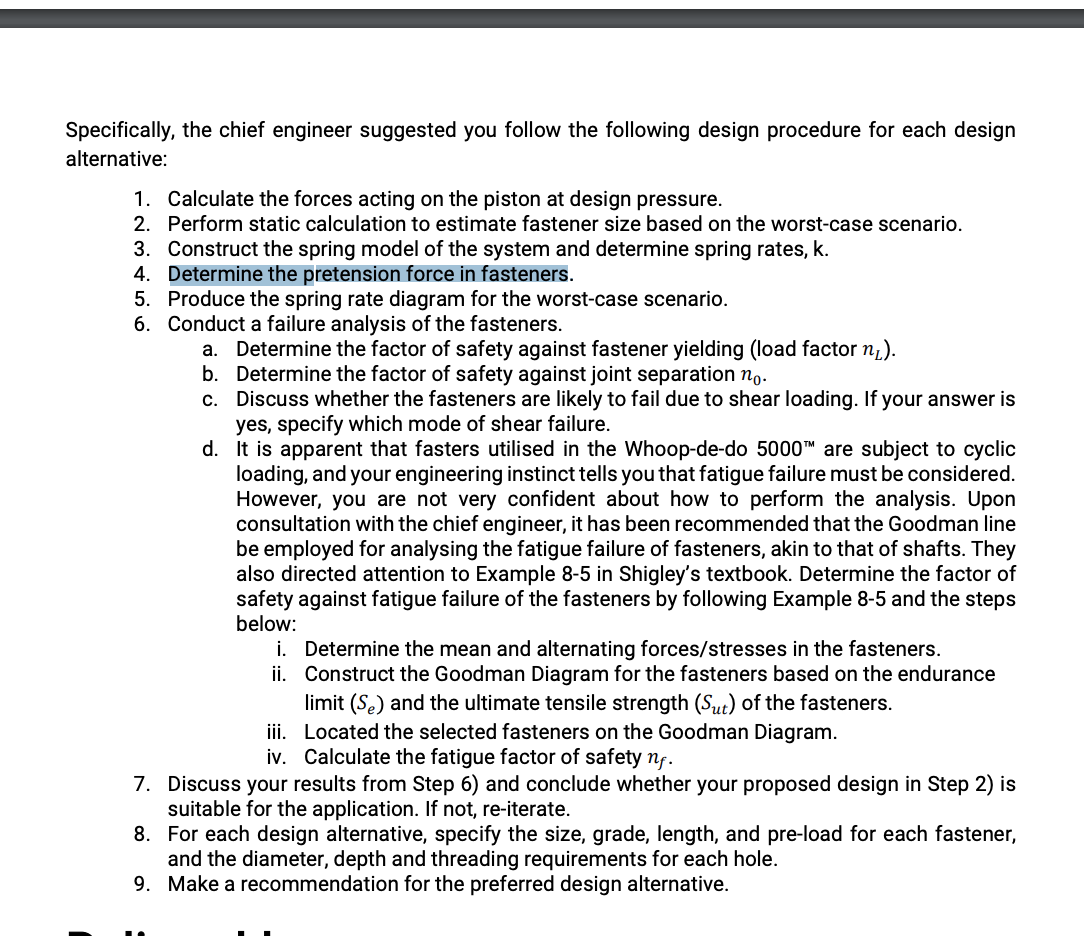
Relevant specs for the Whoop-de-do 5000 are summarised in Table 1. Keep this confidential until the official launch event! Table 1 Specifications of the Whoop-de-do 5000 engine. Engine Specifications Capacity Bore Stroke Head Material Thickness Cylinder Material (a) Alternative 1 (b) Alternative 2 Figure 1. Schematic layout of alternative engine construction. Wall Thickness Length Flange thickness Tapped pylons Crankcase Material Tapped pylons Gaskets Crankcase Head Combustion Pressure Normal Badly tuned Page 2 250 cc 70 mm 64 mm Aluminium 333 25 mm nominal Grade 300 Cast Iron -EN-GLJ-300 3 mm 135 mm between flange faces 8 mm top and bottom 20 mm thick if required Aluminium 333 20 mm thick None 1 mm Aluminium 1.1 MPa 2.0 MPa UNSW SYDNEY Specifically, the chief engineer suggested you follow the following design procedure for each design alternative: 1. Calculate the forces acting on the piston at design pressure. 2. Perform static calculation to estimate fastener size based on the worst-case scenario. 3. Construct the spring model of the system and determine spring rates, k. 4. Determine the pretension force in fasteners. 5. Produce the spring rate diagram for the worst-case scenario. 6. Conduct a failure analysis of the fasteners. a. Determine the factor of safety against fastener yielding (load factor n). b. Determine the factor of safety against joint separation no. c. Discuss whether the fasteners are likely to fail due to shear loading. If your answer is yes, specify which mode of shear failure. d. It is apparent that fasters utilised in the Whoop-de-do 5000 are subject to cyclic loading, and your engineering instinct tells you that fatigue failure must be considered. However, you are not very confident about how to perform the analysis. Upon consultation with the chief engineer, it has been recommended that the Goodman line be employed for analysing the fatigue failure of fasteners, akin to that of shafts. They also directed attention to Example 8-5 in Shigley's textbook. Determine the factor of safety against fatigue failure of the fasteners by following Example 8-5 and the steps below: ii. i. Determine the mean and alternating forces/stresses in the fasteners. Construct the Goodman Diagram for the fasteners based on the endurance limit (Se) and the ultimate tensile strength (Sut) of the fasteners. iii. Located the selected fasteners on the Goodman Diagram. iv. Calculate the fatigue factor of safety nf. 7. Discuss your results from Step 6) and conclude whether your proposed design in Step 2) is suitable for the application. If not, re-iterate. 8. For each design alternative, specify the size, grade, length, and pre-load for each fastener, and the diameter, depth and threading requirements for each hole. 9. Make a recommendation for the preferred design alternative.
Step by Step Solution
There are 3 Steps involved in it
Step: 1

Get Instant Access to Expert-Tailored Solutions
See step-by-step solutions with expert insights and AI powered tools for academic success
Step: 2

Step: 3

Ace Your Homework with AI
Get the answers you need in no time with our AI-driven, step-by-step assistance
Get Started


