

Answered step by step
Verified Expert Solution
Question
1 Approved Answer
Required information A y 200 mm Z NX B AB N X Fx10 FX NOTE: This is a multi-part question. Once an answer is
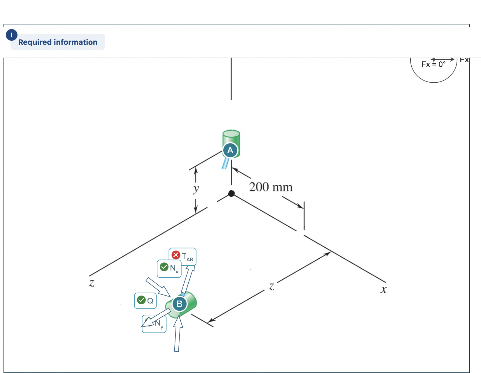
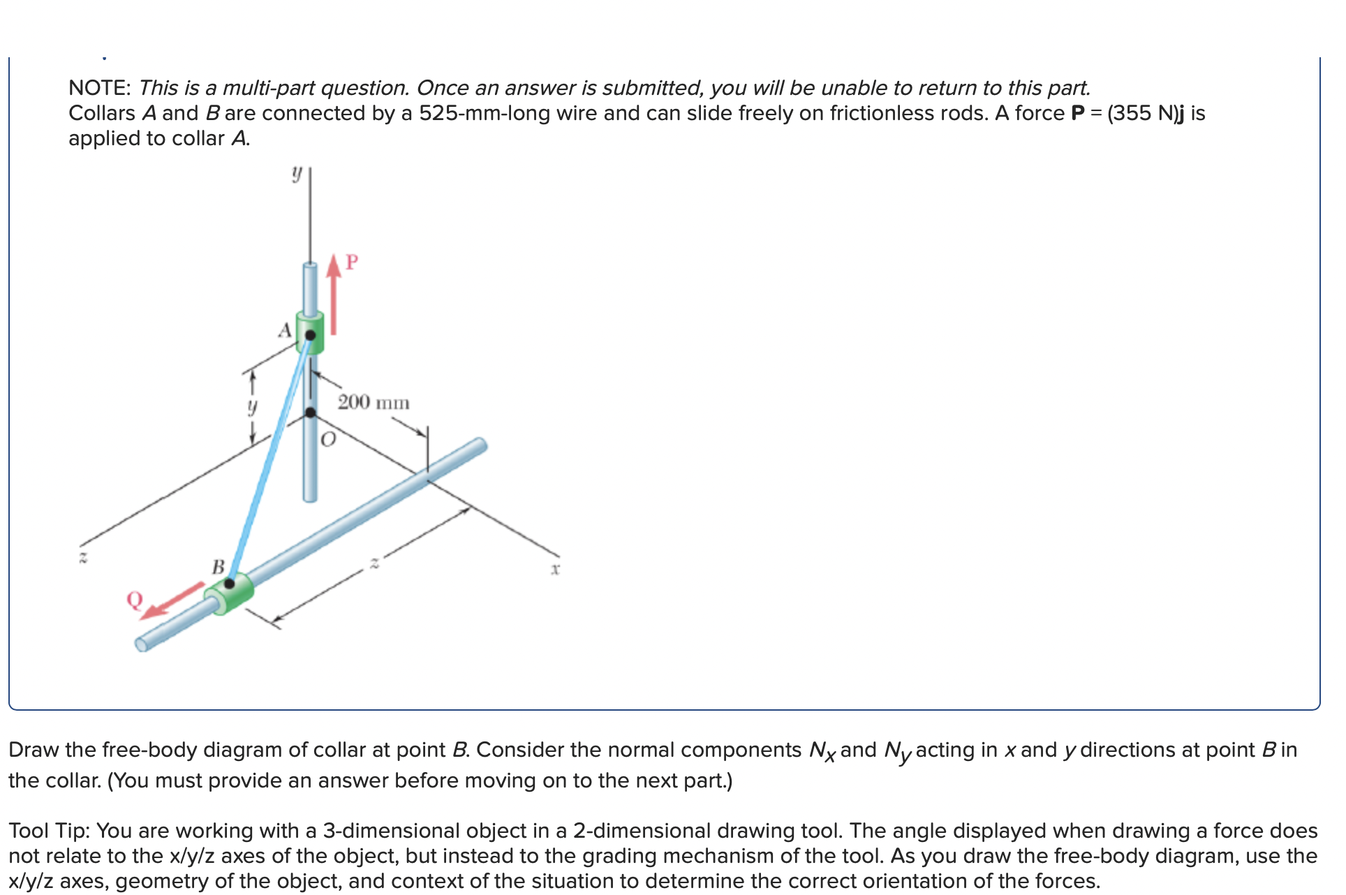
Required information A y 200 mm Z NX B AB N X Fx10 FX NOTE: This is a multi-part question. Once an answer is submitted, you will be unable to return to this part. Collars A and B are connected by a 525-mm-long wire and can slide freely on frictionless rods. A force P = (355 N)j is applied to collar A. B 200 mm I Draw the free-body diagram of collar at point B. Consider the normal components Nx and Ny acting in x and y directions at point B in the collar. (You must provide an answer before moving on to the next part.) Tool Tip: You are working with a 3-dimensional object in a 2-dimensional drawing tool. The angle displayed when drawing a force does not relate to the x/y/z axes of the object, but instead to the grading mechanism of the tool. As you draw the free-body diagram, use the x/y/z axes, geometry of the object, and context of the situation to determine the correct orientation of the forces.
Step by Step Solution
There are 3 Steps involved in it
Step: 1

Get Instant Access to Expert-Tailored Solutions
See step-by-step solutions with expert insights and AI powered tools for academic success
Step: 2

Step: 3
Ace Your Homework with AI
Get the answers you need in no time with our AI-driven, step-by-step assistance
Get Started
Numerical Methods For Engineers
Authors: Steven C. Chapra, Raymond P. Canale
5th Edition
978-0071244299, 0071244298