Question
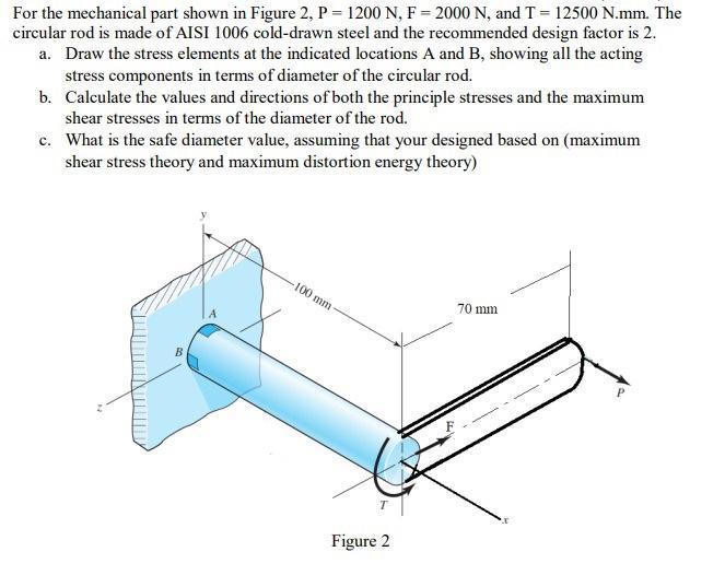
For the mechanical part shown in Figure 2, P = 1200 N, F= 2000 N, and T = 12500 N.mm. The circular rod is

For the mechanical part shown in Figure 2, P = 1200 N, F= 2000 N, and T = 12500 N.mm. The circular rod is made of AISI 1006 cold-drawn steel and the recommended design factor is 2. a. Draw the stress elements at the indicated locations A and B, showing all the acting stress components in terms of diameter of the circular rod. b. Calculate the values and directions of both the principle stresses and the maximum shear stresses in terms of the diameter of the rod. c. What is the safe diameter value, assuming that your designed based on (maximum shear stress theory and maximum distortion energy theory) B 100 mm Figure 2 70 mm
Step by Step Solution
3.42 Rating (158 Votes )
There are 3 Steps involved in it
Step: 1

Get Instant Access to Expert-Tailored Solutions
See step-by-step solutions with expert insights and AI powered tools for academic success
Step: 2

Step: 3

Ace Your Homework with AI
Get the answers you need in no time with our AI-driven, step-by-step assistance
Get StartedRecommended Textbook for
Cost Management A Strategic Emphasis
Authors: Edward Blocher, David F. Stout, Paul Juras, Steven Smith
8th Edition
1259917029, 978-1259917028
Students also viewed these Accounting questions
Question
Answered: 1 week ago
Question
Answered: 1 week ago
Question
Answered: 1 week ago
Question
Answered: 1 week ago
Question
Answered: 1 week ago
Question
Answered: 1 week ago
Question
Answered: 1 week ago
Question
Answered: 1 week ago
Question
Answered: 1 week ago
Question
Answered: 1 week ago
Question
Answered: 1 week ago
Question
Answered: 1 week ago
Question
Answered: 1 week ago
Question
Answered: 1 week ago
Question
Answered: 1 week ago
Question
Answered: 1 week ago
Question
Answered: 1 week ago
View Answer in SolutionInn App


