Answered step by step
Verified Expert Solution
Question
1 Approved Answer
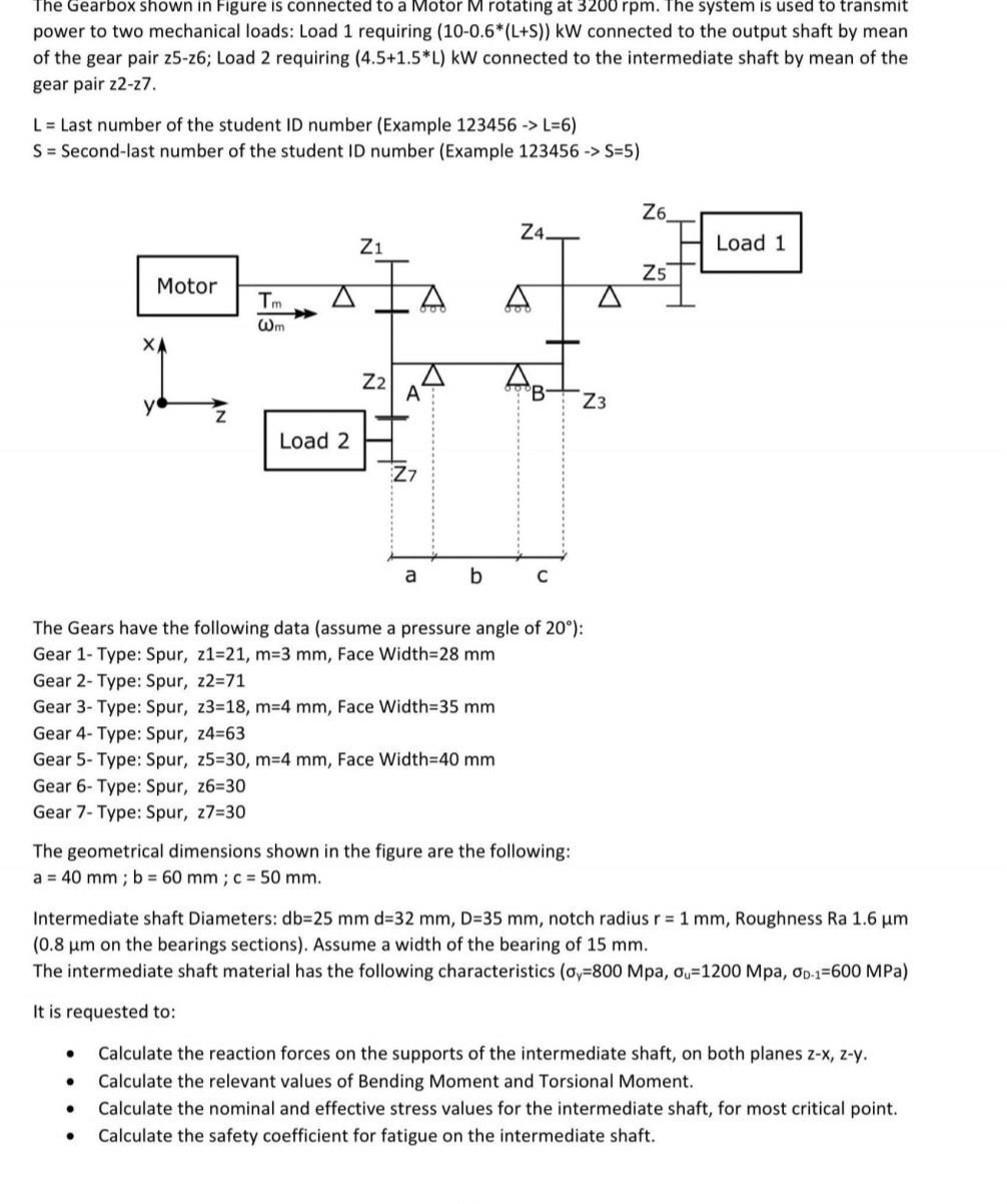
The Gearbox shown in Figure is connected to a Motor M rotating at 3200 rpm. The system is used to transmit power to two


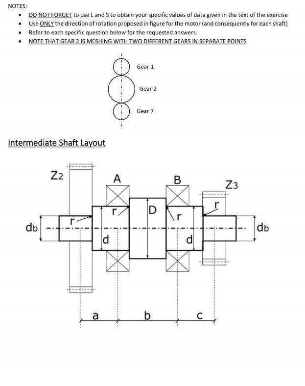
The Gearbox shown in Figure is connected to a Motor M rotating at 3200 rpm. The system is used to transmit power to two mechanical loads: Load 1 requiring (10-0.6*(L+S)) kW connected to the output shaft by mean of the gear pair z5-z6; Load 2 requiring (4.5+1.5*L) kW connected to the intermediate shaft by mean of the gear pair z2-27. L = Last number of the student ID number (Example 123456 -> L=6) S = Second-last number of the student ID number (Example 123456-> S=5) Motor XA Tm Wm Load 2 Z1 Z2 K- A Z7 a b Z4. AB The Gears have the following data (assume a pressure angle of 20): Gear 1- Type: Spur, z1-21, m-3 mm, Face Width=28 mm z2=71 Gear 2- Type: Spur, Gear 3- Type: Spur, z3=18, m-4 mm, Face Width=35 mm Gear 4- Type: Spur, z4=63 Gear 5- Type: Spur, z5=30, m-4 mm, Face Width=40 mm Gear 6- Type: Spur, z6=30 Gear 7- Type: Spur, z7=30 The geometrical dimensions shown in the figure are the following: a = 40 mm; b = 60 mm; c = 50 mm. C A Z3 Z6 Intermediate shaft Diameters: db=25 mm d=32 mm, D=35 mm, notch radius r = 1 mm, Roughness Ra 1.6 m. (0.8 m on the bearings sections). Assume a width of the bearing of 15 mm. The intermediate shaft material has the following characteristics (o,-800 Mpa, o, 1200 Mpa, Op-1-600 MPa) It is requested to: Z5 Calculate the reaction forces on the supports of the intermediate shaft, on both planes z-x, z-y. Calculate the relevant values of Bending Moment and Torsional Moment. Calculate the nominal and effective stress values for the intermediate shaft, for most critical point. Calculate the safety coefficient for fatigue on the intermediate shaft. Load 1 NOTES: DO NOT FORGET to use L and S to obtain your specific values of data given in the text of the exercise Use ONLY the direction of rotation proposed in figure for the motor (and consequently for each shaft) Refer to each specific question below for the requested answers. NOTE THAT GEAR 2 IS MESHING WITH TWO DIFFERENT GEARS IN SEPARATE POINTS Intermediate Shaft Layout db Z I a ld A r Gear 1 Gear 2 Gear 7 D b B d C Z3 i db
Step by Step Solution
★★★★★
3.51 Rating (158 Votes )
There are 3 Steps involved in it
Step: 1
St...
Get Instant Access to Expert-Tailored Solutions
See step-by-step solutions with expert insights and AI powered tools for academic success
Step: 2

Step: 3

Ace Your Homework with AI
Get the answers you need in no time with our AI-driven, step-by-step assistance
Get Started


