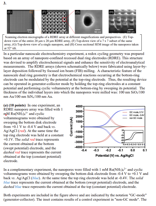
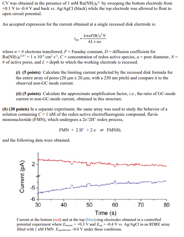
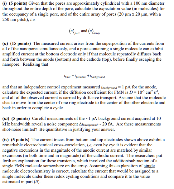
Scanning electron micrographs of a RDRE array at different magnifications and perspectives. (E) Topdown view of the entire 20m20m RDRE array, (F) Top-down view of a 77 subset of the same array, (G) Top-down view of a single nanopore, and (H) Cross sectional SEM image of the nanopores taken at 52 tilt. In a particular nanoscale electrochemistry experiment, a redox cycling geometry was prepared based on an array of nanopore-confined recessed dual ring electrodes (RDRE). This structure was devised to amplify electrochemical signals and enhance the sensitivity of electroanalytical measurements. The RDRE arrays (shown schematically below) were fabricated using layer-bylayer deposition followed by focused ion beam (FIB) milling. A characteristic feature of the nanoscale dual ring geometry is that electrochemical reactions occurring at the bottom-ring electrode can be modulated by the potential at the top-ring electrode. Thus, the resulting device can be operated in generator-collector mode by holding the top-ring electrodes at a constant potential and performing cyclic voltammetry at the bottom-ring by sweeping its potential. The thickness of the individual layers into which the nanopores were milled was: 100nmSiO2/100 (a) (10 points) In one experiment, an RDRE nanopore array was filled with 1 mMRu(NH3)63+ and cyclic voltammograms were obtained by sweeping the bottom disk electrode from +0.1V to 0.4V and back vs. Ag/AgCl(red). At the same time the top ring electrode was held at a constant +0.1V. The solid red trace represents the current obtained at the bottom (swept potential) electrode, and the dashed red trace represents the current obtained at the top (constant potential) electrode. In a complementary experiment, the nanopores were filled with 1mMRu(NH3)62+ and cyclic voltammograms were obtained by sweeping the bottom disk electrode from 0.4V to +0.1V and back vs. Ag/AgCl (blue). At the same time the top ring electrode was held at 0.4V. The solid blue trace represents the current obtained at the bottom (swept potential) electrode, and the dashed blue trace represents the current obtained at the top (constant potential) electrode. Both experiments are included in the figure above and are indicated by the notation "GC-mode" (generator-collector). The inset contains results of a control experiment in "non-GC mode". The CV was obtained in the presence of 1mMRu(NH3)63+ by sweeping the bottom electrode from +0.1V to 0.4V and back vs.Ag/AgCl (black) while the top electrode was allowed to float to open circuit potential. An accepted expression for the current obtained at a single recessed disk electrode is: ilim=4L+a4nFDCa2N where n= \# electrons transferred, F= Faraday constant, D= diffusion coefficient for Ru(NH3)62/3+=1105cm2s1,C= concentration of redox active species, a= pore diameter, N= \# of active pores, and L= depth to which the working electrode is recessed. (i) (5 points) Calculate the limiting current predicted by the recessed disk formula for the entire array of pores ( 20m20m, with a 250nm pitch) and compare it to the observed non-GC mode current. (ii) (5 points) Calculate the approximate amplification factor, i.e., the ratio of GC-mode current to non-GC-mode current, obtained in this structure. (b) (30 points) In a separate experiment, the same array was used to study the behavior of a solution containing C=1nM of the redox-active electrofluorogenic compound, flavin mononucleotide (FMN), which undergoes a 2e/2H+redox process, FMN+2H++2eFMNH2 and the following data were obtained. Current at the bottom (red) and at the top (blue) ring electrodes obtained in a controlled potential experiment where Ebottom=+0.3V and Etop=0.4V vs. Ag/AgCl in an RDRE array filled with 1nM FMN. Eequilbrium0.0V under these conditions. (i) (5 points) Given that the pores are approximately cylindrical with a 100nm diameter throughout the entire depth of the pore, calculate the expectation value (in molecules) for the occupancy of a single pore, and of the entire array of pores (20m20m, with a 250nm pitch), i.e. nporeandnarray (ii) (15 points) The measured current arises from the superposition of the currents from all of the nanopores simultaneously, and a pore containing a single molecule can exhibit amplified current at the bottom electrode only if that molecule repeatedly diffuses back and forth between the anode (bottom) and the cathode (top), before finally escaping the nanopore. Realizing that itotal=ifaradaic+ibacckgroumd and that an independent control experiment measured ibackground=1pA for the anode, calculate the expected current, if the diffusion coefficient for FMN is D=105cm2s1, and all of the observed current is carried by diffusive transport. Assume that the molecule shas to move from the center of one ring electrode to the center of the other electrode and back in order to complete a cycle. (iii) (5 points) Careful measurements of the 1 pA background current acquired at 10 kHz bandwidth reveal a noise component ibackground20 fA. Are these measurements shot-noise limited? Be quantitative in justifying your answer. (iv) (5 points) The current traces from bottom and top electrodes shown above exhibit a remarkable electrochemical cross-correlation, i.e. even by eye it is evident that the negative excursions in the magnitude of the anodic current are matched by similar excursions (in both time and in magnitude) of the cathodic current. The researchers put forth an explanation for these transients, which involved the addition/subtraction of a single FMN molecule somewhere on the array. Assuming this explanation of single molecule electrochemistry is correct, calculate the current that would be assigned to a single molecule under these redox cycling conditions and compare it to the value estimated in part (ii)