Question
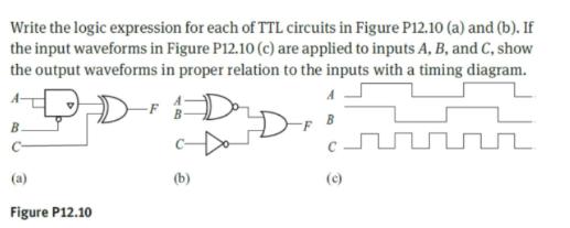
Write the logic expression for each of TTL circuits in Figure P12.10 (a) and (b). If the input waveforms in Figure P12.10 (c) are

Write the logic expression for each of TTL circuits in Figure P12.10 (a) and (b). If the input waveforms in Figure P12.10 (c) are applied to inputs A, B, and C, show the output waveforms in proper relation to the inputs with a timing diagram. B. (a) Figure P12.10 F (b) (c)
Step by Step Solution
3.41 Rating (164 Votes )
There are 3 Steps involved in it
Step: 1

Get Instant Access to Expert-Tailored Solutions
See step-by-step solutions with expert insights and AI powered tools for academic success
Step: 2

Step: 3

Ace Your Homework with AI
Get the answers you need in no time with our AI-driven, step-by-step assistance
Get StartedRecommended Textbook for
Intermediate Accounting
Authors: Donald E. Kieso, Jerry J. Weygandt, and Terry D. Warfield
15th edition
978-1118159644, 9781118562185, 1118159640, 1118147294, 978-1118147290
Students also viewed these Electrical Engineering questions
Question
Answered: 1 week ago
Question
Answered: 1 week ago
Question
Answered: 1 week ago
Question
Answered: 1 week ago
Question
Answered: 1 week ago
Question
Answered: 1 week ago
Question
Answered: 1 week ago
Question
Answered: 1 week ago
Question
Answered: 1 week ago
Question
Answered: 1 week ago
Question
Answered: 1 week ago
Question
Answered: 1 week ago
Question
Answered: 1 week ago
Question
Answered: 1 week ago
Question
Answered: 1 week ago
Question
Answered: 1 week ago
Question
Answered: 1 week ago
Question
Answered: 1 week ago
Question
Answered: 1 week ago
Question
Answered: 1 week ago
Question
Answered: 1 week ago
Question
Answered: 1 week ago
View Answer in SolutionInn App


