Question
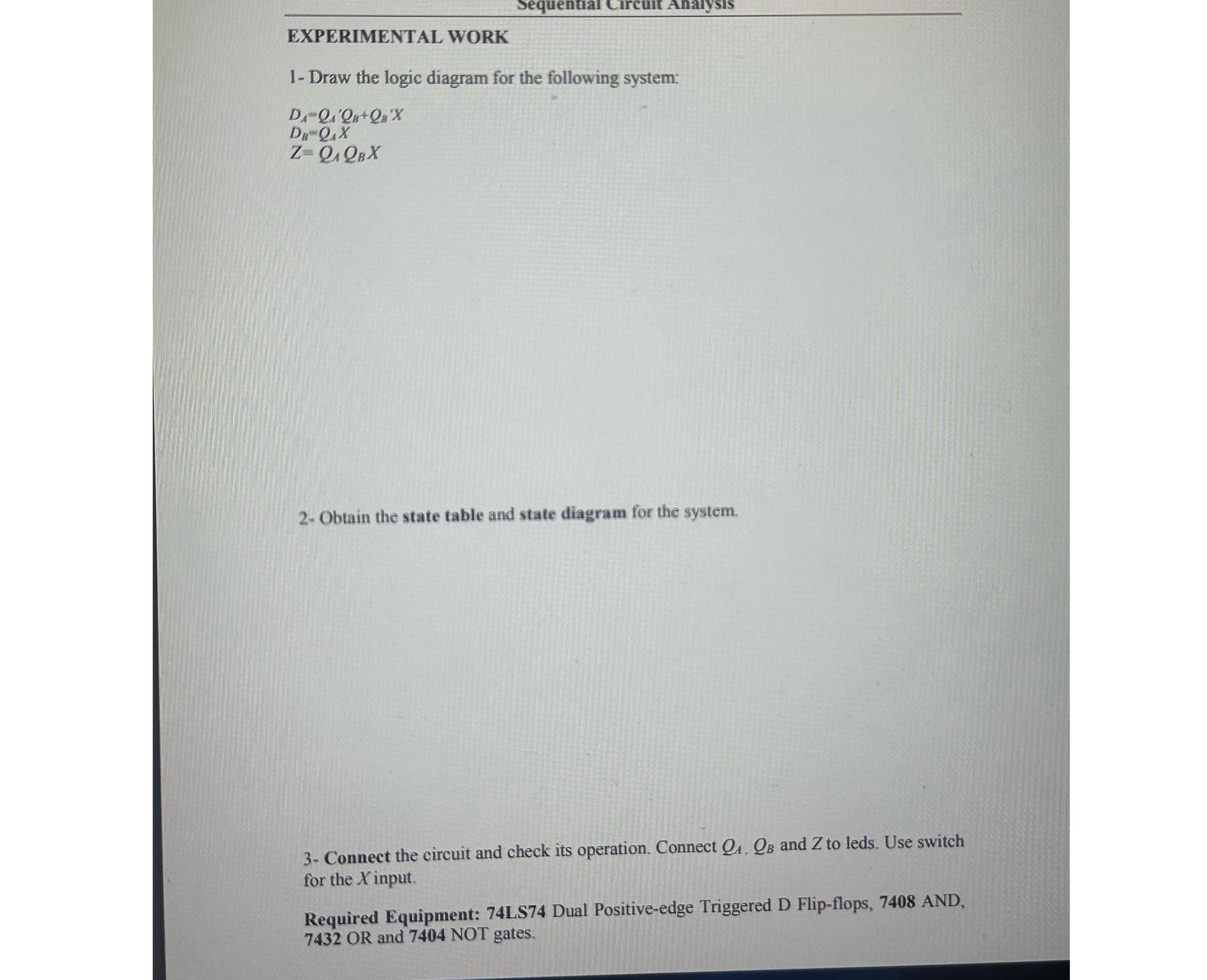
Sequential Circuit Analysis EXPERIMENTAL WORK 1- Draw the logic diagram for the following system: DA-QA'Q+QaX D- QAX Z=QQBX 2- Obtain the state table and

Sequential Circuit Analysis EXPERIMENTAL WORK 1- Draw the logic diagram for the following system: DA-QA'Q+QaX D- QAX Z=QQBX 2- Obtain the state table and state diagram for the system. 3- Connect the circuit and check its operation. Connect Q, QB and Z to leds. Use switch for the X input. Required Equipment: 74LS74 Dual Positive-edge Triggered D Flip-flops, 7408 AND, 7432 OR and 7404 NOT gates.
Step by Step Solution
There are 3 Steps involved in it
Step: 1
1 Logic Diagram DA QA QA QB X QA QA Z 2 State Table and State Diagram State Table DA QA QB X QA QA Q...
Get Instant Access to Expert-Tailored Solutions
See step-by-step solutions with expert insights and AI powered tools for academic success
Step: 2

Step: 3

Ace Your Homework with AI
Get the answers you need in no time with our AI-driven, step-by-step assistance
Get StartedRecommended Textbook for
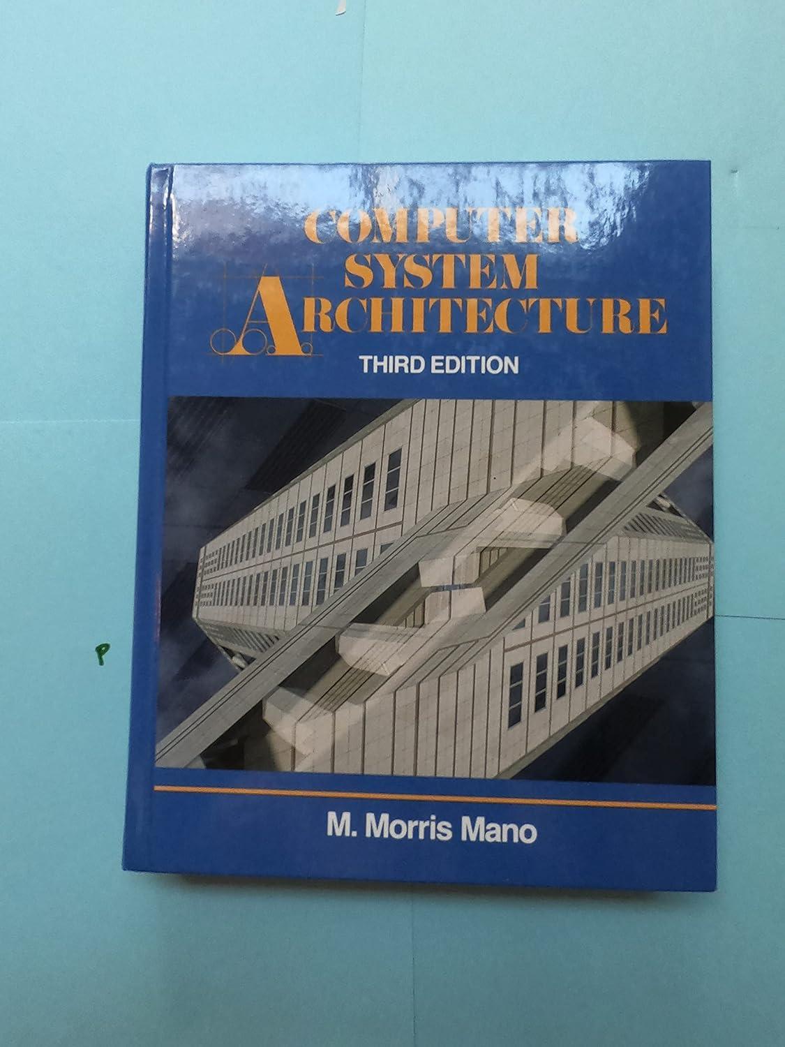
Computer System Architecture
Authors: M. Morris Mano
3rd Edition
0131755633, 978-0131755635
Students also viewed these Programming questions
Question
Answered: 1 week ago
Question
Answered: 1 week ago
Question
Answered: 1 week ago
Question
Answered: 1 week ago
Question
Answered: 1 week ago
Question
Answered: 1 week ago
Question
Answered: 1 week ago
Question
Answered: 1 week ago
Question
Answered: 1 week ago
Question
Answered: 1 week ago
Question
Answered: 1 week ago
Question
Answered: 1 week ago
Question
Answered: 1 week ago
Question
Answered: 1 week ago
Question
Answered: 1 week ago
Question
Answered: 1 week ago
Question
Answered: 1 week ago
Question
Answered: 1 week ago
Question
Answered: 1 week ago
Question
Answered: 1 week ago
Question
Answered: 1 week ago
Question
Answered: 1 week ago
View Answer in SolutionInn App


