

Question: Set up the truth table (table 2 below) for the circuit shown in Figure 1, with (W X Y Z) as inputs and (A B
- Set up the truth table (table 2 below) for the circuit shown in Figure 1, with (W X Y Z) as inputs and (A B C D E F G) as outputs.
Table2: BCD to 7 Segment Decoder truth table
| Decimal | BCD (WXYZ) | A | B | C | D | E | F | G |
| 0 | 0 0 0 0 |
|
|
|
|
|
|
|
| 1 | 0 0 0 1 |
|
|
|
|
|
|
|
| 2 | 0 0 1 0 |
|
|
|
|
|
|
|
| 3 | 0 0 1 1 |
|
|
|
|
|
|
|
| 4 | 0 1 0 0 |
|
|
|
|
|
|
|
| 5 | 0 1 0 1 |
|
|
|
|
|
|
|
| 6 | 0 1 1 0 |
|
|
|
|
|
|
|
| 7 | 0 1 1 1 |
|
|
|
|
|
|
|
| 8 | 1 0 0 0 |
|
|
|
|
|
|
|
| 9 |
|
|
|
|
|
|
|
|
- Find the simplest Boolean expression for each segment from the table above and summarize them in table 3 below.
Table3: Boolean expressions for the 7 segment display cathodes
| Segment | Boolean expression |
| A |
|
| B |
|
| C |
|
| D |
|
| E |
|
| F |
|
| G |
|
- Refer to the FPGA board data sheet to find the 7 segment display cathodes
- Write a Verilog code for a circuit that will perform the function of the BCD-7segment display. You will have 4 inputs to represent BCD number and 7 outputs to control the 7 segments cathodes. Dont forget to enable the anode of the 7 segment that you will use and disable the rest.
- Simulate the circuit in Viva
 do and check the functionality. (You can consider 3 cases for simulation)
 - Implement the circuit and test it in your FPGA board. Check functionality.
- Observe and record the output in the first 7 segment display for combinations 0000 through 1001.
- Observe and record the output displayed of the six unused input combinations 1010 through 1111.
- Show your codes, simulation results and screenshots of 3 testing cases in your report with your comments.

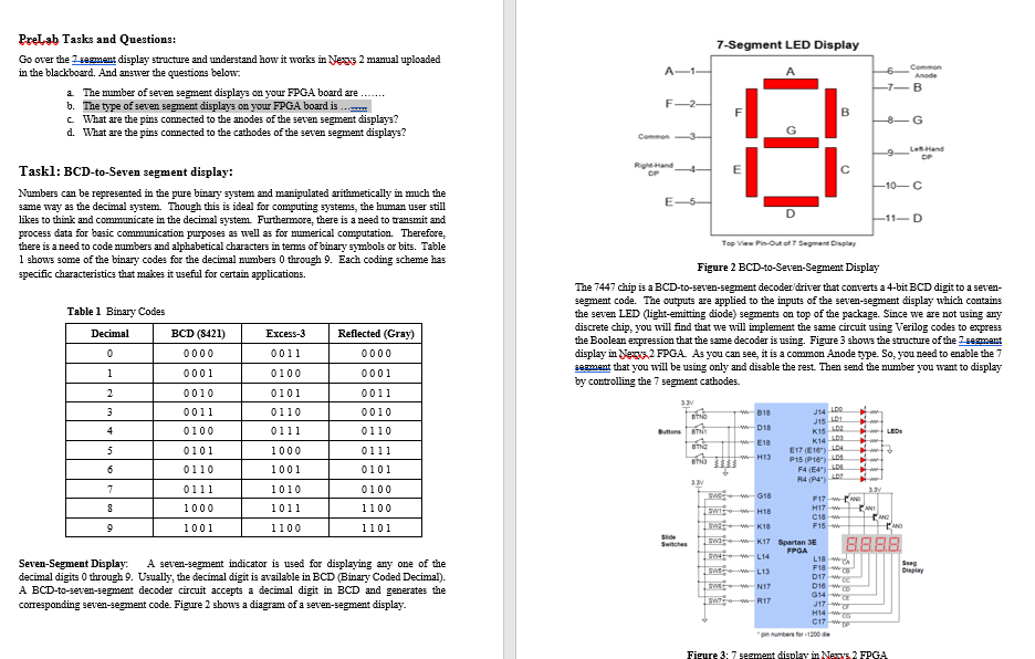
7-Segment LED Display A-12 PreLab Tasks and Questions: Go over the segment display structure and understand how it works in Nexus 2 manual uploaded in the blackboard. And answer the questions below: a The number of seven segment displays on your FPGA board are b. The type of seven segment displays on your FPGA board is c What are the pins connected to the anodes of the seven segment displays? d. What are the pins connected to the cathodes of the seven segment displays? Anode -7B F2 F B 8G Common 3 0 E OP OP E -10-C E5 Taskl: BCD-to-Seven segment display: Numbers can be represented in the pure binary system and manipulated arithmetically in much the same way as the decimal system. Though this is ideal for computing systems, the human user still likes to think and communicate in the decimal system Furthermore, there is a need to transmit and process data for basic communication purposes as well as for numerical computation. Therefore, there is a need to code numbers and alphabetical characters in terms of binary symbols or bits. Table 1 shows some of the binary codes for the decimal numbers 0 through 9. Each coding scheme has specific characteristics that makes it useful for certain applications. -11-D Table 1 Binary Codes Decimal Excess-3 BCD (8421) 0000 Reflected (Gray) 0000 0 Top View in Out of 7 segment Display Figure 2 BCD-to-Seven-Segment Display The 7447 chip is a BCD-to-seven-segment decoder driver that converts a 4-bit BCD digit to a seven- segment code. The outputs are applied to the inputs of the seven-segment display which contains the seven LED (light-emitting diode) segments on top of the package. Since we are not using any discrete chip, you will find that we will implement the same circuit using Verilog codes to express the Boolean expression that the same decoder is using. Figure 3 shows the structure of the sezmant display in Newz.2 FPGA. As you can see, it is a common Anode type. So, you need to enable the 7 segment that you will be using only and disable the rest. Then send the number you want to display by controlling the 7 segment cathodes. 33 le 018 LEDS E18 Bhd - H13 1 0011 0100 0101 0001 0001 2 3 0010 0011 0100 0110 0111 0011 0010 0110 4 J14 LDP JTS DE K15 LDA K14 5 0101 0110 1000 1001 0111 0101 6 E17 (16) PIS (P1) LDA R4 (64) DE R44" LDP 7 0111 1000 1010 1011 0100 1100 8 9 1001 1100 1101 23 3 wors--G18 F17 WAND H17 w TANI H18 C18w F15 AND SW-K17 Spartan SE 3.8.8.8. FPGA L14 L18W Song F18W L13 017 Display N17 016 w 014 w SW-WR17 J17 Seven-Segment Display: A seven-segment indicator is used for displaying any one of the decimal digits 0 through 9. Usually, the decimal digit is available in BCD (Binary Coded Decimal). A BCD-to-seven-segment decoder circuit accepts a decimal digit in BCD and generates the corresponding seven-segment code. Figure 2 shows a diagram of a seven-segment display. H14 C17 W imbers for 1200 de Figure 3: 7 segment display in Ness 2 FPGA 1. Set up the truth table (table 2 below) for the circuit shown in Figure 1, with (WXYZ) as inputs and (ABCDEFG) as outputs. Table2: BCD to 7 Segment Decoder truth table Decimal BCD (WXYZ B D E F 0 0000 1 0001 2 0010 3 0011 4 0100 5 0101 6 0110 7 0111 8 1000 9 1001 2. Find the simplest Boolean expression for each segment from the table above and summarize them in table 3 below. Table3: Boolean expressions for the 7 segment display cathodes Segment Boolean expression A B C D E F 3. Refer to the FPGA board data sheet to find the 7 segment display cathodes 4. Write a Verilog code for a circuit that will perform the function of the BCD-7segment display. You will have 4 inputs to represent BCD number and 7 outputs to control the 7 segments cathodes. Don't forget to enable the anode of the 7 sement that you will use and disable the rest. 5. Simulate the circuit in vivade and check the functionality. (You can consider 3 cases for simulation) 6. Implement the circuit and test it in your FPGA board. Check functionality. 7. Observe and record the output in the first 7 segment display for combinations 0000 through 1001. 8. Observe and record the output displayed of the six urused input combinations 1010 through 1111. 9. Show your codes, simulation results and screenshots of 3 testing cases in your report with your comments
Step by Step Solution
There are 3 Steps involved in it

Get step-by-step solutions from verified subject matter experts