

Answered step by step
Verified Expert Solution
Question
1 Approved Answer
Show analytically that the torque of this motor is proportional to the square of the armature current. PLEASE use pspice 3. The BJT Q in
 Show analytically that the torque of this motor is proportional to the square of the armature current.
PLEASE use pspice
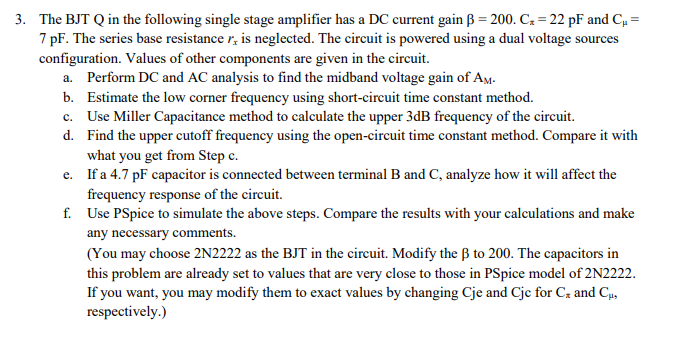
3. The BJT Q in the following single stage amplifier has a DC current gain B = 200. Cs = 22 pF and Cu = 7 pF. The series base resistance r, is neglected. The circuit is powered using a dual voltage sources configuration. Values of other components are given in the circuit. a. Perform DC and AC analysis to find the midband voltage gain of Am. b. Estimate the low corner frequency using short-circuit time constant method. c. Use Miller Capacitance method to calculate the upper 3dB frequency of the circuit. d. Find the upper cutoff frequency using the open-circuit time constant method. Compare it with what you get from Step c. e. If a 4.7 pF capacitor is connected between terminal B and C, analyze how it will affect the frequency response of the circuit. f. Use PSpice to simulate the above steps. Compare the results with your calculations and make any necessary comments. (You may choose 2N2222 as the BJT in the circuit. Modify the 3 to 200. The capacitors in this problem are already set to values that are very close to those in PSpice model of 2N2222. If you want, you may modify them to exact values by changing Cje and Cje for Cz and Cu, respectively.) RC RB1 10K Voc 600k 9V C th 10u 10k B CB th 2u Q2N2222 RL 10k 0 Rsig Vsig VEE CE RB2 9V 300k th 50u RE 5k CE circuit for Problem 3. 3. The BJT Q in the following single stage amplifier has a DC current gain B = 200. Cs = 22 pF and Cu = 7 pF. The series base resistance r, is neglected. The circuit is powered using a dual voltage sources configuration. Values of other components are given in the circuit. a. Perform DC and AC analysis to find the midband voltage gain of Am. b. Estimate the low corner frequency using short-circuit time constant method. c. Use Miller Capacitance method to calculate the upper 3dB frequency of the circuit. d. Find the upper cutoff frequency using the open-circuit time constant method. Compare it with what you get from Step c. e. If a 4.7 pF capacitor is connected between terminal B and C, analyze how it will affect the frequency response of the circuit. f. Use PSpice to simulate the above steps. Compare the results with your calculations and make any necessary comments. (You may choose 2N2222 as the BJT in the circuit. Modify the 3 to 200. The capacitors in this problem are already set to values that are very close to those in PSpice model of 2N2222. If you want, you may modify them to exact values by changing Cje and Cje for Cz and Cu, respectively.) RC RB1 10K Voc 600k 9V C th 10u 10k B CB th 2u Q2N2222 RL 10k 0 Rsig Vsig VEE CE RB2 9V 300k th 50u RE 5k CE circuit for Problem 3Step by Step Solution
There are 3 Steps involved in it
Step: 1

Get Instant Access to Expert-Tailored Solutions
See step-by-step solutions with expert insights and AI powered tools for academic success
Step: 2

Step: 3
Ace Your Homework with AI
Get the answers you need in no time with our AI-driven, step-by-step assistance
Get Started
Intermediate Accounting
Authors: Donald E. Kieso, Jerry J. Weygandt, Terry D. Warfield
IFRS edition volume 2
978-0470613474, 470613475, 978-0470616314