

Answered step by step
Verified Expert Solution
Question
1 Approved Answer
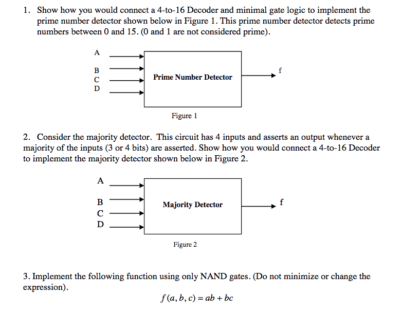
Show how you would connect a 4-to-16 Decoder and minimal gate logic to implement the prime number detector shown below in Figure 1. This prime
Step by Step Solution
There are 3 Steps involved in it
Step: 1

Get Instant Access to Expert-Tailored Solutions
See step-by-step solutions with expert insights and AI powered tools for academic success
Step: 2

Step: 3
Ace Your Homework with AI
Get the answers you need in no time with our AI-driven, step-by-step assistance
Get Started
Database Systems For Advanced Applications Dasfax 2009 International Workshops Benchmark Mcis Wdpp Ppda Mbc Phd Brisbane Australia April 2009 Lncs 5667
Authors: Lei Chen ,Chengfei Liu ,Qing Liu ,Ke Deng
2009th Edition
364204204X, 978-3642042041