

Answered step by step
Verified Expert Solution
Question
1 Approved Answer
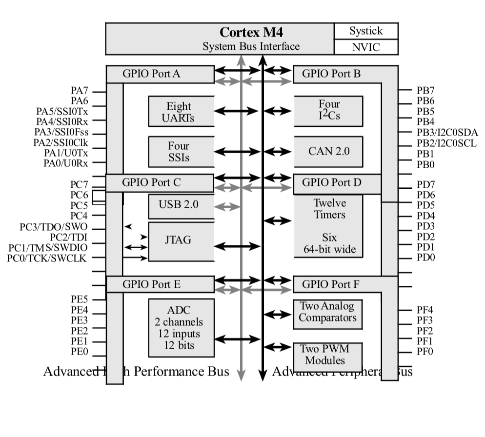
Show the circuit diagram to interface a switch to PA6 and an LED to PC3. Write software that initializes the ports. In the body of
Show the circuit diagram to interface a switch to PA6 and an LED to PC3. Write software that initializes the ports. In the body of the main program, toggle the LED on and off if the switch is pressed, and turn the LED off if the switch is not pressed
Step by Step Solution
There are 3 Steps involved in it
Step: 1

Get Instant Access to Expert-Tailored Solutions
See step-by-step solutions with expert insights and AI powered tools for academic success
Step: 2

Step: 3
Ace Your Homework with AI
Get the answers you need in no time with our AI-driven, step-by-step assistance
Get Started
Deductive And Object Oriented Databases Second International Conference Dood 91 Munich Germany December 18 1991 Proceedings Lncs 566
Authors: Claude Delobel ,Michael Kifer ,Yoshifumi Masunaga
1st Edition