Answered step by step
Verified Expert Solution
Link Copied!

Question

1 Approved Answer

shown below represents the hardware that implements the following 9- The block diagram microoperations: (abc'+ abc.); R1 R2. (abe+abc): R1 R1 + R2 R1 Complementer
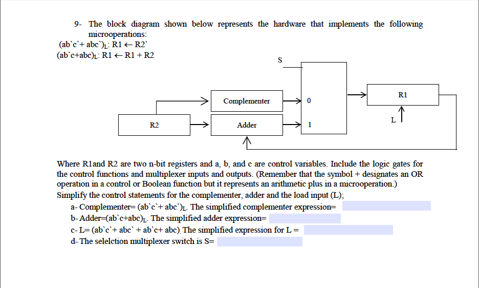
image text in transcribed

shown below represents the hardware that implements the following 9- The block diagram microoperations: (abc'+ abc.); R1 R2. (abe+abc): R1 R1 + R2 R1 Complementer R2 Adder Where R1and R2 are two n-bit registers and a, b, and c are control variables. Include the logic gates for the control functions and multiplexer inputs and outputs. (Remember that the symbol + designates an OR operation in a control or Boolean function but it represents an arithmetic plus in a microoperation.) Simplify the control statements for the complementer, adder and the load input (L); a-Complementer= (abc+ aber The simplified complementer expression b-Adder(abctabOn The simplified adder expression= C-L= (abc't abc' + abc+ abc) The simplified expression for L = d-The selection multiplexer switch is S=

Step by Step Solution

There are 3 Steps involved in it

Step: 1

blur-text-image

Get Instant Access to Expert-Tailored Solutions

See step-by-step solutions with expert insights and AI powered tools for academic success

Step: 2

blur-text-image_2

Step: 3

blur-text-image_3

Ace Your Homework with AI

Get the answers you need in no time with our AI-driven, step-by-step assistance

Get Started

Students also viewed these Databases questions

Question

6.3 Discuss negotiation strategies and solutions at work

Answered: 1 week ago

Question

f. Did they change their names? For what reasons?

Answered: 1 week ago