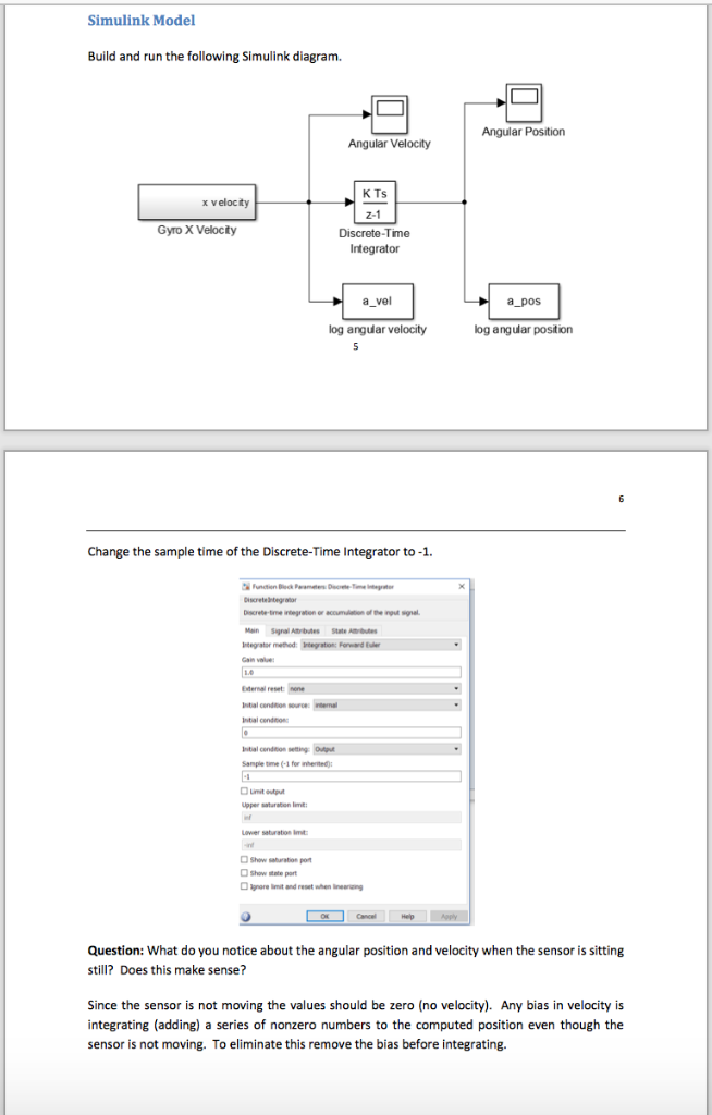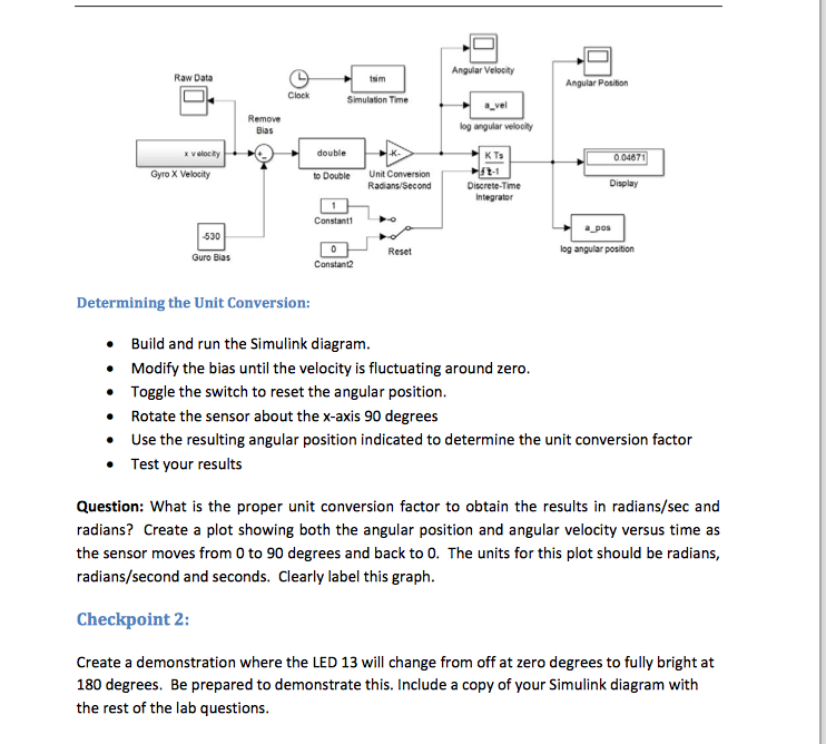

Simulink Model Build and run the following Simulink diagram. Angular Position Angular Velocity K TS x velocity Gyro X Velocty Discrete-Time Integrator a_vel a_pos log anguiar velocity og angular position Change the sample time of the Discrete-Time Integrator to -1. ternal reset: Upper sataration lmt Lower saturation imt Show sraton po Show itale por Question: What do you notice about the angular position and velocity when the sensor is sitting still? Does this make sense? Since the sensor is not moving the values should be zero (no velocity). Any bias in velocity is integrating (adding) a series of nonzero numbers to the computed position even though the sensor is not moving. To eliminate this remove the bias before integrating. Angular Velocity Raw Data Angular Position a_vel Remove Bias og angular veloolty x velocity double K Ts 0.04871 Unit Conversion Radians/Second Gyro X Velocity to Double Discrete-Time Display Constanto Reset og angular position Guro Bias Constant Determining the Unit Conversion: Build and run the Simulink diagram Modify the bias until the velocity is fluctuating around zero Toggle the switch to reset the angular position Rotate the sensor about the x-axis 90 degrees Use the resulting angular position indicated to determine the unit conversion factor Test your results . Question: What is the proper unit conversion factor to obtain the results in radians/sec and radians? Create a plot showing both the angular position and angular velocity versus time as the sensor moves from 0 to 90 degrees and back to 0. The units for this plot should be radians, radians/second and seconds. Clearly label this graph Checkpoint 2: Create a demonstration where the LED 13 will change from off at zero degrees to fully bright at 180 degrees. Be prepared to demonstrate this. Include a copy of your Simulink diagram with the rest of the lab questions Simulink Model Build and run the following Simulink diagram. Angular Position Angular Velocity K TS x velocity Gyro X Velocty Discrete-Time Integrator a_vel a_pos log anguiar velocity og angular position Change the sample time of the Discrete-Time Integrator to -1. ternal reset: Upper sataration lmt Lower saturation imt Show sraton po Show itale por Question: What do you notice about the angular position and velocity when the sensor is sitting still? Does this make sense? Since the sensor is not moving the values should be zero (no velocity). Any bias in velocity is integrating (adding) a series of nonzero numbers to the computed position even though the sensor is not moving. To eliminate this remove the bias before integrating. Angular Velocity Raw Data Angular Position a_vel Remove Bias og angular veloolty x velocity double K Ts 0.04871 Unit Conversion Radians/Second Gyro X Velocity to Double Discrete-Time Display Constanto Reset og angular position Guro Bias Constant Determining the Unit Conversion: Build and run the Simulink diagram Modify the bias until the velocity is fluctuating around zero Toggle the switch to reset the angular position Rotate the sensor about the x-axis 90 degrees Use the resulting angular position indicated to determine the unit conversion factor Test your results . Question: What is the proper unit conversion factor to obtain the results in radians/sec and radians? Create a plot showing both the angular position and angular velocity versus time as the sensor moves from 0 to 90 degrees and back to 0. The units for this plot should be radians, radians/second and seconds. Clearly label this graph Checkpoint 2: Create a demonstration where the LED 13 will change from off at zero degrees to fully bright at 180 degrees. Be prepared to demonstrate this. Include a copy of your Simulink diagram with the rest of the lab questions


