

Question
Sketch the state transition diagram for the FSM described by the following SystemVerilog code. module fsm2( input logic clk, reset, input logic a, b, output
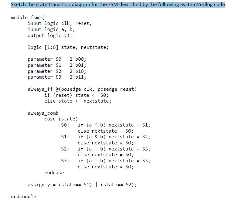
Sketch the state transition diagram for the FSM described by the following SystemVerilog code.
module fsm2( input logic clk, reset, input logic a, b, output logic y); logic [1:0] state, nextstate; parameter S0 = 2'b00; parameter S1 = 2'b01; parameter S2 = 2'b10; parameter S3 = 2'b11; always_ff @(posedge clk, posedge reset) if (reset) state
Step by Step Solution
There are 3 Steps involved in it
Step: 1

Get Instant Access to Expert-Tailored Solutions
See step-by-step solutions with expert insights and AI powered tools for academic success
Step: 2

Step: 3
Ace Your Homework with AI
Get the answers you need in no time with our AI-driven, step-by-step assistance
Get Started
Advances In Spatial Databases 5th International Symposium Ssd 97 Berlin Germany July 15 18 1997 Proceedings Lncs 1262
Authors: Michel Scholl ,Agnes Voisard
1st Edition
3540632387, 978-3540632382