

Answered step by step
Verified Expert Solution
Question
1 Approved Answer
solve all 6 parts of the question by LTspice. Simulating some of diode and transistor circuits: 1. Voltage Multiplier Circuits: Vin C1 az VO L19
solve all 6 parts of the question by LTspice.
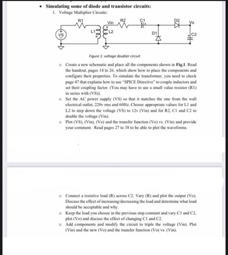
Simulating some of diode and transistor circuits: 1. Voltage Multiplier Circuits: Vin C1 az VO L19 Vs D1 c2 Figure 1: voltage doubler circuit Create a new schematic and place all the components shown in Fig.1. Read the handout, pages 14 to 26, which show how to place the components and configure their properties. To simulate the transformer, you need to check page 47 that explains how to use "SPICE Directive" to couple inductors and set their coupling factor. (You may have to use a small value resistor (RI) in series with (VS)). Set the AC power supply (VS) so that it matches the one from the wall electrical outlet, 220v mms and 60Hz. Choose appropriate values for Ll and L2 to step down the voltage (VS) to 12v (Vin) and for R2, CI and C2 to double the voltage (Vin). Plot (VS), (Vin). (Vo) and the transfer function (Vo) vs. (Vin) and provide your comment. Read pages 27 to 38 to be able to plot the waveforms Connect a resistive load (R) across C2. Vary (R) and plot the output (Vo). Discuss the effect of increasing/decreasing the load and determine what load should be acceptable and why. Keep the load you choose in the previous step constant and vary Cl and C2, plot (Vo) and discuss the effect of changing CI and C2. Add components and modify the circuit to triple the voltage (Vin). Plot (Vin) and the new (Vo) and the transfer function (Vo) vs. (Vin). Simulating some of diode and transistor circuits: 1. Voltage Multiplier Circuits: Vin C1 az VO L19 Vs D1 c2 Figure 1: voltage doubler circuit Create a new schematic and place all the components shown in Fig.1. Read the handout, pages 14 to 26, which show how to place the components and configure their properties. To simulate the transformer, you need to check page 47 that explains how to use "SPICE Directive" to couple inductors and set their coupling factor. (You may have to use a small value resistor (RI) in series with (VS)). Set the AC power supply (VS) so that it matches the one from the wall electrical outlet, 220v mms and 60Hz. Choose appropriate values for Ll and L2 to step down the voltage (VS) to 12v (Vin) and for R2, CI and C2 to double the voltage (Vin). Plot (VS), (Vin). (Vo) and the transfer function (Vo) vs. (Vin) and provide your comment. Read pages 27 to 38 to be able to plot the waveforms Connect a resistive load (R) across C2. Vary (R) and plot the output (Vo). Discuss the effect of increasing/decreasing the load and determine what load should be acceptable and why. Keep the load you choose in the previous step constant and vary Cl and C2, plot (Vo) and discuss the effect of changing CI and C2. Add components and modify the circuit to triple the voltage (Vin). Plot (Vin) and the new (Vo) and the transfer function (Vo) vs. (Vin)Step by Step Solution
There are 3 Steps involved in it
Step: 1

Get Instant Access to Expert-Tailored Solutions
See step-by-step solutions with expert insights and AI powered tools for academic success
Step: 2

Step: 3
Ace Your Homework with AI
Get the answers you need in no time with our AI-driven, step-by-step assistance
Get Started
Graph Databases
Authors: Ian Robinson, Jim Webber, Emil Eifrem
1st Edition
1449356265, 978-1449356262