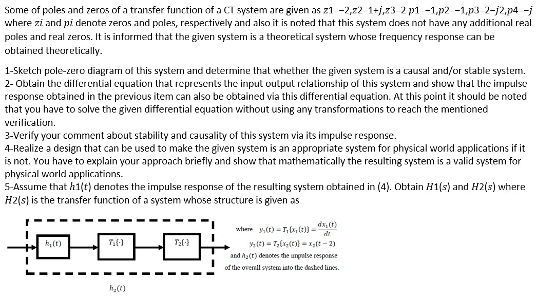
Some of poles and zeros of a transfer function of a CT system are given as z1=-2,22=1+j,z3=2 p1=-1,p2=-1,p3=212,p4=-j where zi and pi denote zeros and poles, respectively and also it is noted that this system does not have any additional real poles and real zeros. It is informed that the given system is a theoretical system whose frequency response can be obtained theoretically. 1-Sketch pole-zero diagram of this system and determine that whether the given system is a causal and/or stable system. 2- Obtain the differential equation that represents the input output relationship of this system and show that the impulse response obtained in the previous item can also be obtained via this differential equation. At this point it should be noted that you have to solve the given differential equation without using any transformations to reach the mentioned verification. 3-Verify your comment about stability and causality of this system via its impulse response. 4-Realize a design that can be used to make the given system is an appropriate system for physical world applications if it is not. You have to explain your approach briefly and show that mathematically the resulting system is a valid system for physical world applications. 5-Assume that hi(t) denotes the impulse response of the resulting system obtained in (4). Obtain H1(s) and H2(s) where H2(s) is the transfer function of a system whose structure is given as h(t) Tio T200 dxit) where y(t) =T_{x}(t)} = dt yz(t) = T2{xz(t)} = x2(t-2) and h(t) denotes the impulse response of the overall system into the dashed lines. hz(t) Some of poles and zeros of a transfer function of a CT system are given as z1=-2,22=1+j,z3=2 p1=-1,p2=-1,p3=212,p4=-j where zi and pi denote zeros and poles, respectively and also it is noted that this system does not have any additional real poles and real zeros. It is informed that the given system is a theoretical system whose frequency response can be obtained theoretically. 1-Sketch pole-zero diagram of this system and determine that whether the given system is a causal and/or stable system. 2- Obtain the differential equation that represents the input output relationship of this system and show that the impulse response obtained in the previous item can also be obtained via this differential equation. At this point it should be noted that you have to solve the given differential equation without using any transformations to reach the mentioned verification. 3-Verify your comment about stability and causality of this system via its impulse response. 4-Realize a design that can be used to make the given system is an appropriate system for physical world applications if it is not. You have to explain your approach briefly and show that mathematically the resulting system is a valid system for physical world applications. 5-Assume that hi(t) denotes the impulse response of the resulting system obtained in (4). Obtain H1(s) and H2(s) where H2(s) is the transfer function of a system whose structure is given as h(t) Tio T200 dxit) where y(t) =T_{x}(t)} = dt yz(t) = T2{xz(t)} = x2(t-2) and h(t) denotes the impulse response of the overall system into the dashed lines. hz(t)


