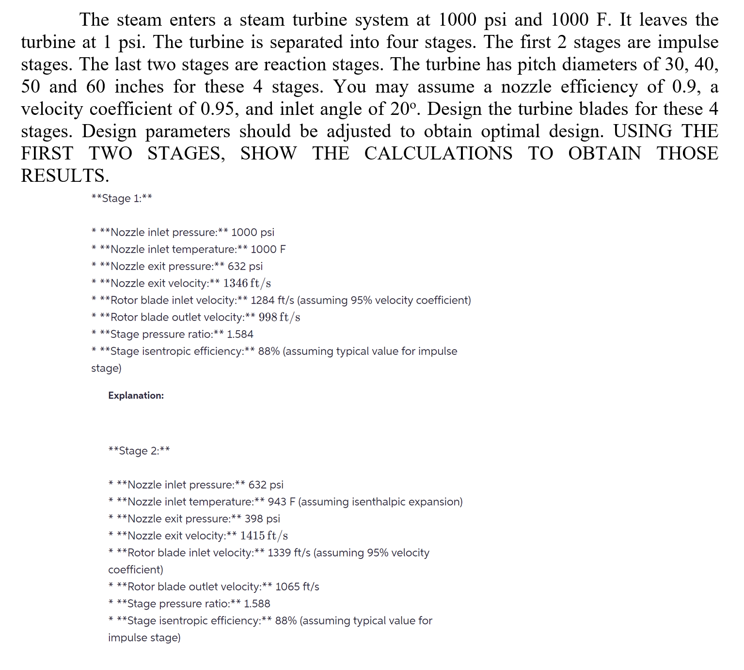
Answered step by step
Verified Expert Solution
Link Copied!

Question

1 Approved Answer

** Stage 1:^(****) * 1000 psi * 1000F * 632 psi ***Nozzle exit velocity: ^(****)1346f(t)/(s) *** Rotor blade inlet velocity:** 1284f(t)/(s) (assuming

** Stage

1:^(****)

\ * 1000 psi\ *

1000F

\ * 632 psi\ ***Nozzle exit velocity:

^(****)1346f(t)/(s)

\ *** Rotor blade inlet velocity:**

1284f(t)/(s)

(assuming 95% velocity coefficient)\ *** Rotor blade outlet velocity:**

998f(t)/(s)

\ *** Stage pressure ratio:** 1.584\ *** *tage isentropic efficiency:

^(****)88%

(assuming typical value for impulse\ stage)\ Explanation:\

^(****)

Stage

2:****

\ * 632 psi\ *

943F

(assuming isenthalpic expansion)\ ***Nozzle exit pressure:

^(****)398

psi\ ***Nozzle exit velocity:

^(****)1415f(t)/(s)

\ ** Rotor blade inlet velocity:**

1339f(t)/(s)

(assuming 95% velocity\ coefficient)\ *** Rotor blade outlet velocity:**

1065f(t)/(s)

\ *** Stage pressure ratio:

^(****)1.588

\

****

Stage isentropic efficiency:

^(****)88%

(assuming typical value for\ impulse stage)

image text in transcribed
The steam enters a steam turbine system at 1000psi and 1000F. It leaves the turbine at 1 psi. The turbine is separated into four stages. The first 2 stages are impulse stages. The last two stages are reaction stages. The turbine has pitch diameters of 30,40, 50 and 60 inches for these 4 stages. You may assume a nozzle efficiency of 0.9 , a velocity coefficient of 0.95 , and inlet angle of 20. Design the turbine blades for these 4 stages. Design parameters should be adjusted to obtain optimal design. USING THE FIRST TWO STAGES, SHOW THE CALCULATIONS TO OBTAIN THOSE RESULTS. The steam enters a steam turbine system at 1000psi and 1000F. It leaves the turbine at 1 psi. The turbine is separated into four stages. The first 2 stages are impulse stages. The last two stages are reaction stages. The turbine has pitch diameters of 30,40, 50 and 60 inches for these 4 stages. You may assume a nozzle efficiency of 0.9 , a velocity coefficient of 0.95 , and inlet angle of 20. Design the turbine blades for these 4 stages. Design parameters should be adjusted to obtain optimal design. USING THE FIRST TWO STAGES, SHOW THE CALCULATIONS TO OBTAIN THOSE RESULTS

Step by Step Solution

There are 3 Steps involved in it

Step: 1

blur-text-image

Get Instant Access to Expert-Tailored Solutions

See step-by-step solutions with expert insights and AI powered tools for academic success

Step: 2

blur-text-image

Step: 3

blur-text-image

Ace Your Homework with AI

Get the answers you need in no time with our AI-driven, step-by-step assistance

Get Started

Recommended Textbook for

Transport Processes And Separation Process Principles

Authors: Christie Geankoplis, Allen Hersel, Daniel Lepek

5th Edition

0134181026, 978-0134181028

More Books

Students also viewed these Chemical Engineering questions