

Question
Step 1: Basic Configuration Referring to the topology, configure IP addressing and basic configuration for all routers, PCs, server and wireless component Verify the connection.
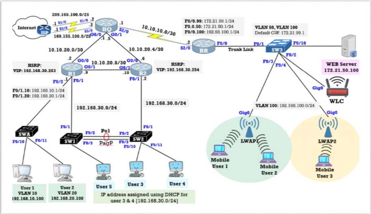
Step 1: Basic Configuration Referring to the topology, configure IP addressing and basic configuration for all routers, PCs, server and wireless component Verify the connection. Step 2: Configure VLAN Create the following VLANs. Names are case-sensitive and must match the requirement exactly (refer to the topology):
VLAN ID NAME 10 IT_Dept 20 Research Dept 50 Server_Farm 100 WLAN_User 99 (All switches) Management 666 (All switches) Native_VLAN
Assign VLANs to the active ports on SW1, SW2 and SW3 to the respective host connected. Verify connectivity between PCs on the same network. Study the output of from the following command on switches and explain it based on your knowledge of communication between VLANS.
Step 3: Configure Trunks Configure trunking on SW1, SW2 and SW3 use VLAN 666 as the native VLAN to replace the default VLAN 1. On SW1, SW2 and SW3, issue the show interface trunk command to confirm that DTP has successfully negotiated trunking with SW1 on SW2 and SW3. The output also displays information about the trunk interfaces on S2 and S3. Discuss the output. Correct the native VLAN mismatch if the error message appear between switches.
Step 4: Configure Router-on-the-stick to enable Inter-VLAN Routing. Configure subinterfaces on router R1 and BR using the 802.1Q encapsulation. Use the show ip interface brief command to verify subinterface configuration. Identify whether status of subinterfaces are up or down. Subinterfaces are virtual interfaces that are associated with a physical interface. Therefore, in order to enable subinterfaces, you must enable the physical interface that they are associated with. Test Connectivity with Inter-VLAN Routing. If the configurations are correct, users should be able to ping their default gateways and each other.
Step 6: Configure an EtherChannel with Cisco PAgP Before beginning the link aggregation between switches, verify the existing configuration of the ports that connect the switches to ensure that the ports will successfully join the EtherChannel. Configure all ports that are required for the EtherChannels as static trunk ports. On SW1 and SW2, add ports F0/21 and F0/22 to Port Channel 1 with the channelgroup 1 mode desirable command. The mode desirable option enables the switch to actively negotiate to form a PAgP link. Issue the show etherchannel summary command on SW1 and SW2 to verify that EtherChannel is working on both switches. This command displays the type of EtherChannel, the ports utilized, and the port states.
Step 7: Configure DHCPv4 Configure a R2 as a DHCP Server to enable IP address can be assigned dynamically to user 3 and user 4 which IP address is VLAN 30. Make sure you exclude the first 10 addresses from the R2 LAN 192.168.30.0/24. Create a DHCP pool named R2-LAN 30 (case-sensitive). Configure R1 as a DHCP relay agent so that user 5 also can be assigned IP address dynamically. Verify DHCP bindings using command R2# show ip dhcp binding. Verify that User 3 and user 4 are assigned with the correct IP address and can ping each other and all other devices.
Step 8: Configure HSRP Active and Standby Routers Trace the path to the Web Server from user 1 and user 3 and need to enable the helper address for the LAN interface on R1. (If fail, state the reason) Configure HSRP on the appropriate interface of R1 and R2 respectively. (Hint: refer to lab exercise HSRP). R2 is an active and R1 as standby router. You may use any related steps and procedure to enable HSRP configuration for network 192.168.30.0/24. The virtual IP address is 192.168.30.254 as a default gateway for user 3, 4 and 5. Use the show standby brief command on R1 and R2 to view an HSRP status summary. Provide the output in the report. Then, to observe HSRP operation make the active router become unavailable. After that verify to view HSRP status
Step 9: Switch Security Configuration Shutdown all unused switch ports on all switches. On SWA, create a VLAN 44 and name it PARKING_LOT. Move all unused switch ports to the PARKING_LOT VLAN. Implement Port Security. o Activate port security on all the active access ports on switch SW-1. o Configure the active ports to allow a maximum of 4 MAC addresses to be learned on the ports. o For ports F0/1 on SW-1, statically configure the MAC address of the PC using port security. o Configure each active access port so that it will automatically add the MAC addresses learned on the port to the running configuration. o Configure the port security violation mode to drop packets from MAC addresses that exceed the maximum, generate a Syslog entry, but not disable the ports. Configure PortFast, and BPDU Guard. o Enable PortFast on all the access ports that are in use on SWA. o Enable BPDU Guard on all the access ports that are in use on SWA.
Step 10: Create a Wireless LAN Configure the wireless LAN controller with a WLAN and it will use WPA2-PSK authentication. You will also configure the WLC to use an SNMP server and configure a DHCP scope that will be used by the wireless management network. Assign an SSID of LAB_ITT532 to the WLAN. Hosts will need to use this SSID to join the network. Connect a Host to the WLAN and verify the connectivity. You need to configure DHCP and permit a maximum of 50 addresses to be issued by the router. Test connectivity between the wireless hosts and the Web Server by ping and URL.
Step 11: Configure IPv4 Static and Floating Static Default Routes Configure IP static croute to enable traffic from HQ can be transmitted to BR router. Verify all users can access webserver. On edge router, HQ, configure a directly connected IPv4 default static route. The primary default route should be through router HQ on interface serial 2/0 and the backup link is another link connected on interface S3/0. Trace the connectivity from user the ISP. Then down the primary link to test whether the floating route is working. Show the traceroute result from any user.
Step by Step Solution
There are 3 Steps involved in it
Step: 1

Get Instant Access to Expert-Tailored Solutions
See step-by-step solutions with expert insights and AI powered tools for academic success
Step: 2

Step: 3
Ace Your Homework with AI
Get the answers you need in no time with our AI-driven, step-by-step assistance
Get Started
DB2 Universal Database V7.1 Application Development Certification Guide
Authors: Steve Sanyal, David Martineau, Kevin Gashyna, Michael Kyprianou
1st Edition
0130913677, 978-0130913678