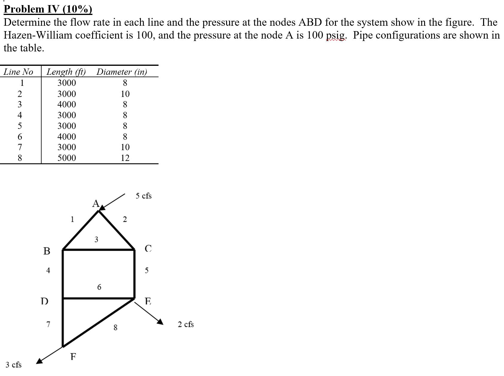
Question: Problem IV (10%) Determine the flow rate in each line and the pressure at the nodes ABD for the system show in the figure.
Problem IV (10%) Determine the flow rate in each line and the pressure at the nodes ABD for the system show in the figure. The Hazen-William coefficient is 100, and the pressure at the node A is 100 psig. Pipe configurations are shown in the table. Line No Length (ft) Diameter (in) 1 3000 8. 2 3000 10 3 4000 8 4 3000 8. 5 3000 8. 4000 8 7 3000 10 8 5000 12 5 cfs A 6 D E 7 2 cfs 8. F 3 cfs
Step by Step Solution
3.46 Rating (156 Votes )
There are 3 Steps involved in it
HazenWilliams Coefficient Range from 130 to 140 Re... View full answer

Get step-by-step solutions from verified subject matter experts


