Answered step by step
Verified Expert Solution
Question
1 Approved Answer
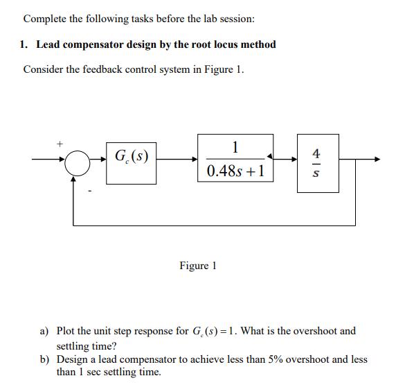
Complete the following tasks before the lab session: 1. Lead compensator design by the root locus method Consider the feedback control system in Figure


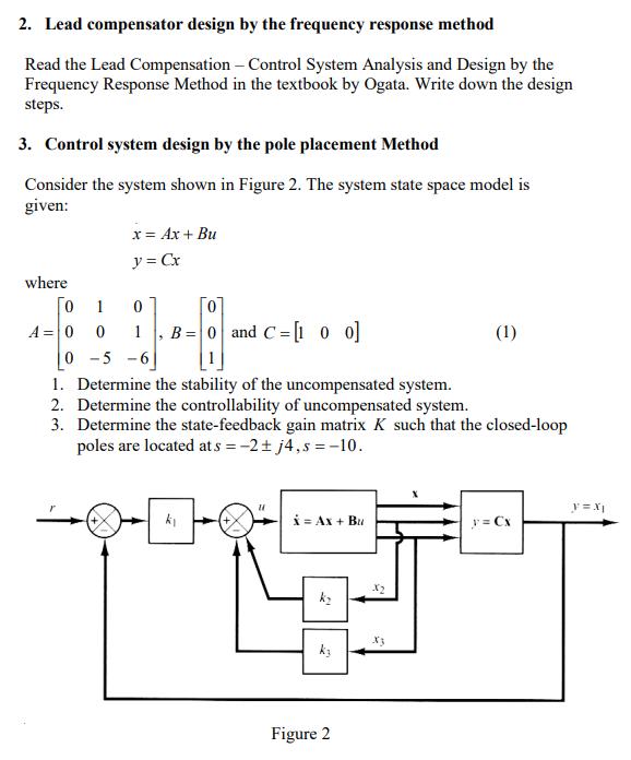
Complete the following tasks before the lab session: 1. Lead compensator design by the root locus method Consider the feedback control system in Figure 1. + 1 0.48s +1 PET G.(s) Figure 1 4 S a) Plot the unit step response for G (s) = 1. What is the overshoot and settling time? b) Design a lead compensator to achieve less than 5% overshoot and less than 1 sec settling time. 2. Lead compensator design by the frequency response method Read the Lead Compensation - Control System Analysis and Design by the Frequency Response Method in the textbook by Ogata. Write down the design steps. 3. Control system design by the pole placement Method Consider the system shown in Figure 2. The system state space model is given: where A = 0 x = Ax + Bu y = Cx 1 0 0 -5 -6 1. Determine the stability of the uncompensated system. 2. Determine the controllability of uncompensated system. 3. Determine the state-feedback gain matrix K such that the closed-loop poles are located at s = -2j4,s = -10. 0 0 1 B = 0 and C=[100] k 11 x = AX + Bu ky ky Figure 2 X2 (1) y = Cx y=Xj
Step by Step Solution
★★★★★
3.44 Rating (157 Votes )
There are 3 Steps involved in it
Step: 1

Get Instant Access to Expert-Tailored Solutions
See step-by-step solutions with expert insights and AI powered tools for academic success
Step: 2

Step: 3

Ace Your Homework with AI
Get the answers you need in no time with our AI-driven, step-by-step assistance
Get Started


