Answered step by step
Verified Expert Solution
Question
1 Approved Answer
take L = 10 m and Z= 0.5. Please do it carefully and give solution step by step Oil is required to be transferred from


take L = 10 m and Z= 0.5. Please do it carefully and give solution step by step
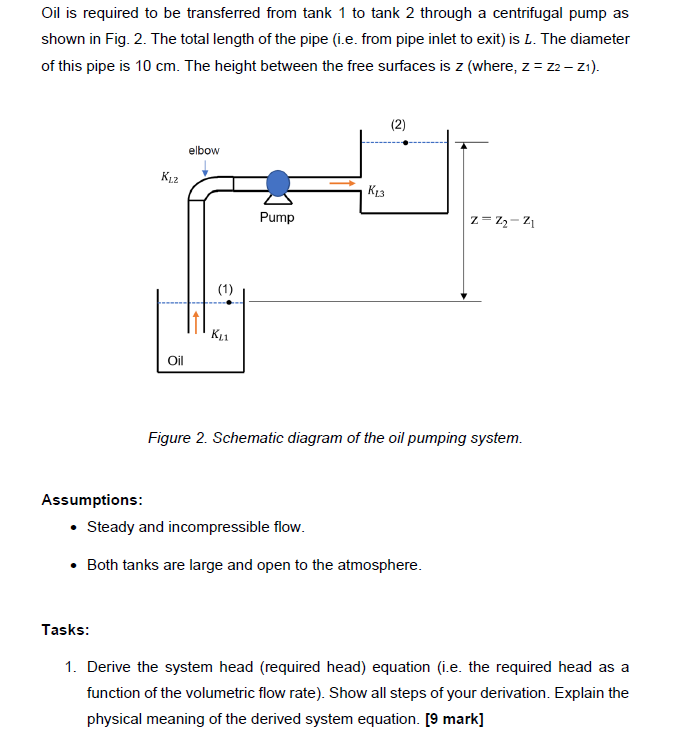
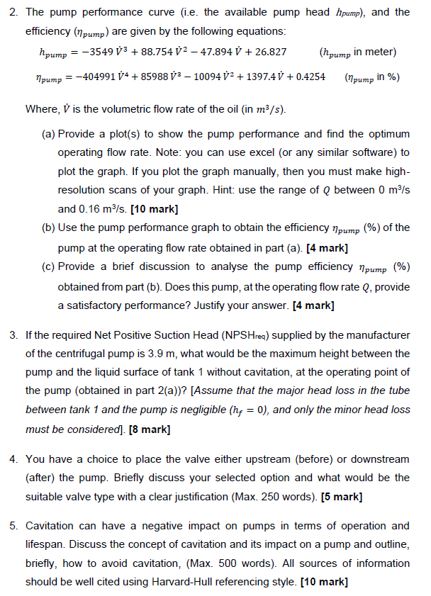
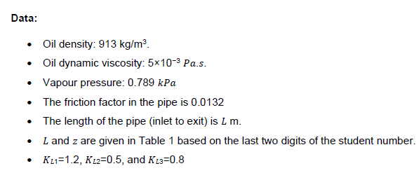
Oil is required to be transferred from tank 1 to tank 2 through a centrifugal pump as shown in Fig. 2. The total length of the pipe (i.e. from pipe inlet to exit) is L. The diameter of this pipe is 10cm. The height between the free surfaces is z (where, z=z2z1 ). Figure 2. Schematic diagram of the oil pumping system. Assumptions: - Steady and incompressible flow. - Both tanks are large and open to the atmosphere. Tasks: 1. Derive the system head (required head) equation (i.e. the required head as a function of the volumetric flow rate). Show all steps of your derivation. Explain the physical meaning of the derived system equation. [9 mark] 2. The pump performance curve (i.e. the available pump head hpump ), and the efficiency (pump) are given by the following equations: hpump=3549V3+88.754V247.894V+26.827(hpumpinmeter)pump=404991V4+85988V310094V2+1397.4V+0.4254(pumpin%) Where, V is the volumetric flow rate of the oil (in m3/s ). (a) Provide a plot(s) to show the pump performance and find the optimum operating flow rate. Note: you can use excel (or any similar software) to plot the graph. If you plot the graph manually, then you must make highresolution scans of your graph. Hint: use the range of Q between 0m3/s and 0.16m3/s. [10 mark] (b) Use the pump performance graph to obtain the efficiency pump(%) of the pump at the operating flow rate obtained in part (a). [4 mark] (c) Provide a brief discussion to analyse the pump efficiency pump (\%) obtained from part (b). Does this pump, at the operating flow rate Q, provide a satisfactory performance? Justify your answer. [4 mark] 3. If the required Net Positive Suction Head (NPSHreq) supplied by the manufacturer of the centrifugal pump is 3.9m, what would be the maximum height between the pump and the liquid surface of tank 1 without cavitation, at the operating point of the pump (obtained in part 2(a))? [Assume that the major head loss in the tube between tank 1 and the pump is negligible (hf=0), and only the minor head loss must be considered]. [8 mark] 4. You have a choice to place the valve either upstream (before) or downstream (after) the pump. Briefly discuss your selected option and what would be the suitable valve type with a clear justification (Max. 250 words). [5 mark] 5. Cavitation can have a negative impact on pumps in terms of operation and lifespan. Discuss the concept of cavitation and its impact on a pump and outline, briefly, how to avoid cavitation, (Max. 500 words). All sources of information should be well cited using Harvard-Hull referencing style. [10 mark] Data: - Oil density: 913kg/m3. - Oil dynamic viscosity: 5103 Pa.s. - Vapour pressure: 0.789kPa - The friction factor in the pipe is 0.0132 - The length of the pipe (inlet to exit) is Lm. - L and z are given in Table 1 based on the last two digits of the student number. - KL1=1.2,KL2=0.5, and KL3=0.8Step by Step Solution
There are 3 Steps involved in it
Step: 1

Get Instant Access to Expert-Tailored Solutions
See step-by-step solutions with expert insights and AI powered tools for academic success
Step: 2

Step: 3

Ace Your Homework with AI
Get the answers you need in no time with our AI-driven, step-by-step assistance
Get Started


