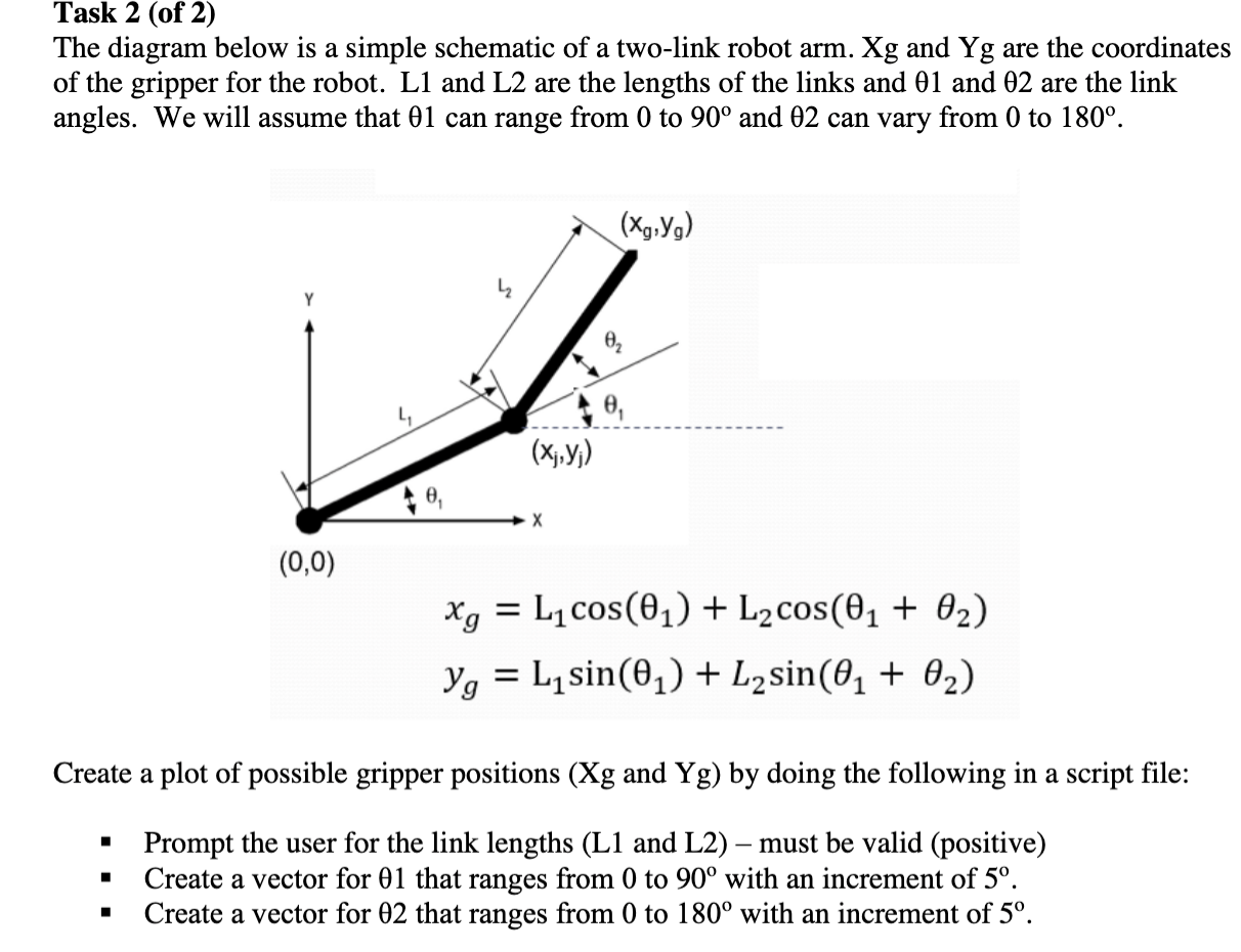
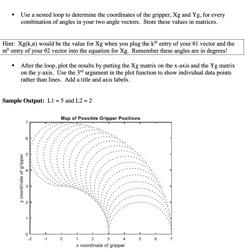
Task 2 (of 2) The diagram below is a simple schematic of a two-link robot arm. Xg and Yg are the coordinates of the gripper for the robot. L1 and L2 are the lengths of the links and 01 and 02 are the link angles. We will assume that 01 can range from 0 to 90 and 02 can vary from 0 to 180. (Xg,yo) e, (X;,y;) (0,0) xg = L cos() + Lacos(2 + 02) yg = L sin() + Lysin(01 + 02) Create a plot of possible gripper positions (Xg and Yg) by doing the following in a script file: Prompt the user for the link lengths (L1 and L2) must be valid (positive) Create a vector for 01 that ranges from 0 to 90 with an increment of 5. Create a vector for 02 that ranges from 0 to 180 with an increment of 5. Use a nested loop to determine the coordinates of the gripper, Xg and Yg, for every combination of angles in your two angle vectors. Store these values in matrices. Hint: Xg(k,n) would be the value for Xg when you plug the kth entry of your 01 vector and the nt" entry of your 02 vector into the equation for Xg. Remember these angles are in degrees! After the loop, plot the results by putting the Xg matrix on the x-axis and the Yg matrix on the y-axis. Use the 3rd argument in the plot function to show individual data points rather than lines. Add a title and axis labels. Sample Output: L1 = 5 and L2 = 2 Map of Possible Gripper Positions 7 6 y coordinate of gripper 1 0 -2 -1 0 5 6 7 1 2 3 4 x coordinate of gripper Task 2 (of 2) The diagram below is a simple schematic of a two-link robot arm. Xg and Yg are the coordinates of the gripper for the robot. L1 and L2 are the lengths of the links and 01 and 02 are the link angles. We will assume that 01 can range from 0 to 90 and 02 can vary from 0 to 180. (Xg,yo) e, (X;,y;) (0,0) xg = L cos() + Lacos(2 + 02) yg = L sin() + Lysin(01 + 02) Create a plot of possible gripper positions (Xg and Yg) by doing the following in a script file: Prompt the user for the link lengths (L1 and L2) must be valid (positive) Create a vector for 01 that ranges from 0 to 90 with an increment of 5. Create a vector for 02 that ranges from 0 to 180 with an increment of 5. Use a nested loop to determine the coordinates of the gripper, Xg and Yg, for every combination of angles in your two angle vectors. Store these values in matrices. Hint: Xg(k,n) would be the value for Xg when you plug the kth entry of your 01 vector and the nt" entry of your 02 vector into the equation for Xg. Remember these angles are in degrees! After the loop, plot the results by putting the Xg matrix on the x-axis and the Yg matrix on the y-axis. Use the 3rd argument in the plot function to show individual data points rather than lines. Add a title and axis labels. Sample Output: L1 = 5 and L2 = 2 Map of Possible Gripper Positions 7 6 y coordinate of gripper 1 0 -2 -1 0 5 6 7 1 2 3 4 x coordinate of gripper