Answered step by step
Verified Expert Solution
Question
1 Approved Answer
Tasneem was designing a pulse rate measuring circuit for his Junior Design Project. After implementing the circuit with a pulse rate sensor, he noticed

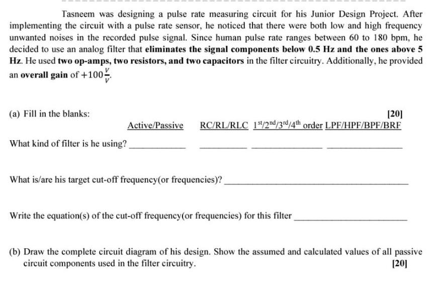
Tasneem was designing a pulse rate measuring circuit for his Junior Design Project. After implementing the circuit with a pulse rate sensor, he noticed that there were both low and high frequency unwanted noises in the recorded pulse signal. Since human pulse rate ranges between 60 to 180 bpm, he decided to use an analog filter that eliminates the signal components below 0.5 Hz and the ones above 5 Hz. He used two op-amps, two resistors, and two capacitors in the filter circuitry. Additionally, he provided an overall gain of +100% (a) Fill in the blanks: Active/Passive RC/RL/RLC 1st/2nd/3rd/4th order LPF/HPF/BPF/BRF What kind of filter is he using? What is/are his target cut-off frequency(or frequencies)? [20] Write the equation(s) of the cut-off frequency (or frequencies) for this filter (b) Draw the complete circuit diagram of his design. Show the assumed and calculated values of all passive circuit components used in the filter circuitry. [20]
Step by Step Solution
★★★★★
3.46 Rating (162 Votes )
There are 3 Steps involved in it
Step: 1
a Active 2nd order Butterworth low pass filter LPF His targ...
Get Instant Access to Expert-Tailored Solutions
See step-by-step solutions with expert insights and AI powered tools for academic success
Step: 2

Step: 3

Ace Your Homework with AI
Get the answers you need in no time with our AI-driven, step-by-step assistance
Get Started


