

Answered step by step
Verified Expert Solution
Question
1 Approved Answer
The answer should not be by handwritten. ITDR3101 Lab 5: Interaction Diagrams: System Sequence Diagram 5.1 Introduction Interaction diagrams describe how groups of objects collaborate
The answer should not be by handwritten.
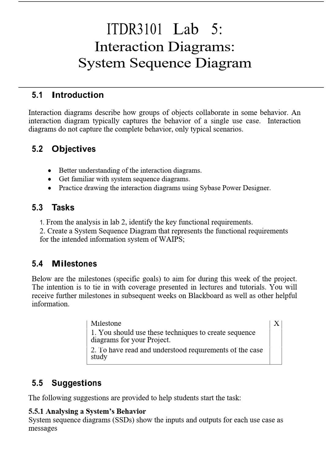
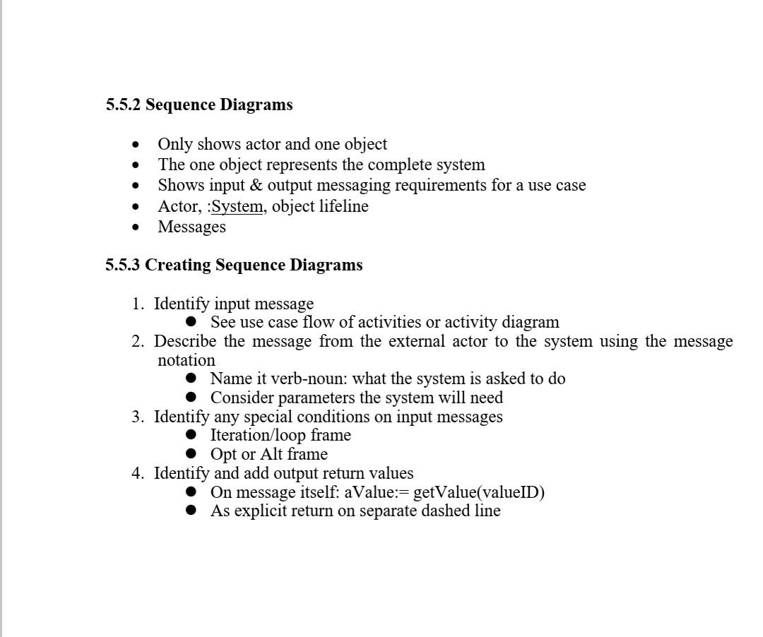
ITDR3101 Lab 5: Interaction Diagrams: System Sequence Diagram 5.1 Introduction Interaction diagrams describe how groups of objects collaborate in some behavior. An interaction diagram typically captures the behavior of a single use case. Interaction diagrams do not capture the complete behavior, only typical scenarios. 5.2 Objectives . Better understanding of the interaction diagrams. Get familiar with system sequence diagrams. Practice drawing the interaction diagrams using Sybase Power Designer. . 5.3 Tasks 1. From the analysis in lab 2, identify the key functional requirements. 2. Create a System Sequence Diagram that represents the functional requirements for the intended information system of WAIPS; 5.4 Milestones Below are the milestones (specific goals) to aim for during this week of the project. The intention is to tie in with coverage presented in lectures and tutorials. You will receive further milestones in subsequent weeks on Blackboard as well as other helpful information. X Milestone 1. You should use these techniques to create sequence diagrams for your Project. 2. To have read and understood requirements of the case study 5.5 Suggestions The following suggestions are provided to help students start the task: 5.5.1 Analysing a System's Behavior System sequence diagrams (SSDs) show the inputs and outputs for each use case as messages 5.5.2 Sequence Diagrams . Only shows actor and one object The one object represents the complete system Shows input & output messaging requirements for a use case Actor, :System, object lifeline Messages 5.5.3 Creating Sequence Diagrams 1. Identify input message See use case flow of activities or activity diagram 2. Describe the message from the external actor to the system using the message notation Name it verb-noun: what the system is asked to do Consider parameters the system will need 3. Identify any special conditions on input messages Iteration/loop frame Opt or Alt frame 4. Identify and add output return values On message itself: aValue:= getValue(valueID) As explicit return on separate dashed lineStep by Step Solution
There are 3 Steps involved in it
Step: 1

Get Instant Access to Expert-Tailored Solutions
See step-by-step solutions with expert insights and AI powered tools for academic success
Step: 2

Step: 3
Ace Your Homework with AI
Get the answers you need in no time with our AI-driven, step-by-step assistance
Get Started
Spatial Database Systems Design Implementation And Project Management
Authors: Albert K.W. Yeung, G. Brent Hall
1st Edition
1402053932, 978-1402053931