Answered step by step
Verified Expert Solution
Question
1 Approved Answer
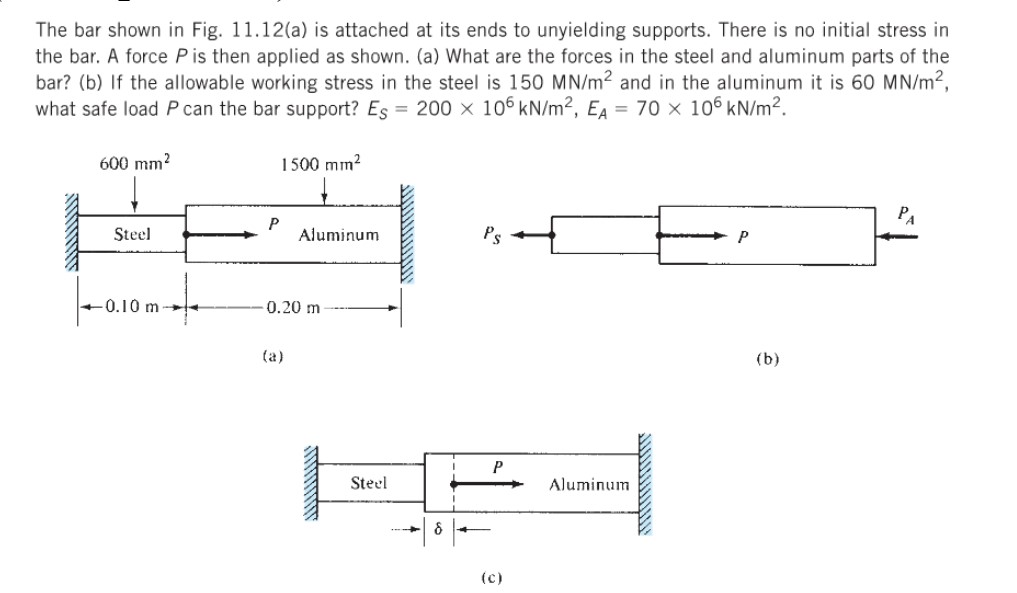
The bar shown in Fig. 11.12(a) is attached at its ends to unyielding supports. There is no initial stress in the bar. A force

The bar shown in Fig. 11.12(a) is attached at its ends to unyielding supports. There is no initial stress in the bar. A force P is then applied as shown. (a) What are the forces in the steel and aluminum parts of the bar? (b) If the allowable working stress in the steel is 150 MN/m and in the aluminum it is 60 MN/m, what safe load P can the bar support? Es = 200 x 106 kN/m, EA = 70 106 kN/m. 600 mm 1500 mm Steel P PA Aluminum Ps P 0.10 m- 10 m 0.20 m (a) P Steel (c) Aluminum (b)
Step by Step Solution
There are 3 Steps involved in it
Step: 1
Solutions Step 1 From the above calculations it is ...
Get Instant Access to Expert-Tailored Solutions
See step-by-step solutions with expert insights and AI powered tools for academic success
Step: 2

Step: 3

Ace Your Homework with AI
Get the answers you need in no time with our AI-driven, step-by-step assistance
Get Started


