Question
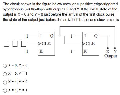
The circuit shown in the figure below uses ideal positive edge-triggered synchronous J-K flip-flops with outputs X and Y. If the initial state of

The circuit shown in the figure below uses ideal positive edge-triggered synchronous J-K flip-flops with outputs X and Y. If the initial state of the output is X = 0 and Y = 0 just before the arrival of the first clock pulse, the state of the output just before the arrival of the second clock pulse is OX=0, Y=0 OX=0, Y = 1 OX= 1, Y=0 OX= 1, Y = 1 J Q CLK K J >CLK K Q 6 X Y Output
Step by Step Solution
3.53 Rating (153 Votes )
There are 3 Steps involved in it
Step: 1
The detailed answe...
Get Instant Access to Expert-Tailored Solutions
See step-by-step solutions with expert insights and AI powered tools for academic success
Step: 2

Step: 3

Ace Your Homework with AI
Get the answers you need in no time with our AI-driven, step-by-step assistance
Get StartedRecommended Textbook for
Modern Control Systems
Authors: Richard C. Dorf, Robert H. Bishop
12th edition
136024580, 978-0136024583
Students also viewed these Physics questions
Question
Answered: 1 week ago
Question
Answered: 1 week ago
Question
Answered: 1 week ago
Question
Answered: 1 week ago
Question
Answered: 1 week ago
Question
Answered: 1 week ago
Question
Answered: 1 week ago
Question
Answered: 1 week ago
Question
Answered: 1 week ago
Question
Answered: 1 week ago
Question
Answered: 1 week ago
Question
Answered: 1 week ago
Question
Answered: 1 week ago
Question
Answered: 1 week ago
Question
Answered: 1 week ago
Question
Answered: 1 week ago
Question
Answered: 1 week ago
Question
Answered: 1 week ago
Question
Answered: 1 week ago
Question
Answered: 1 week ago
Question
Answered: 1 week ago
Question
Answered: 1 week ago
View Answer in SolutionInn App


