Answered step by step
Verified Expert Solution
Question
1 Approved Answer
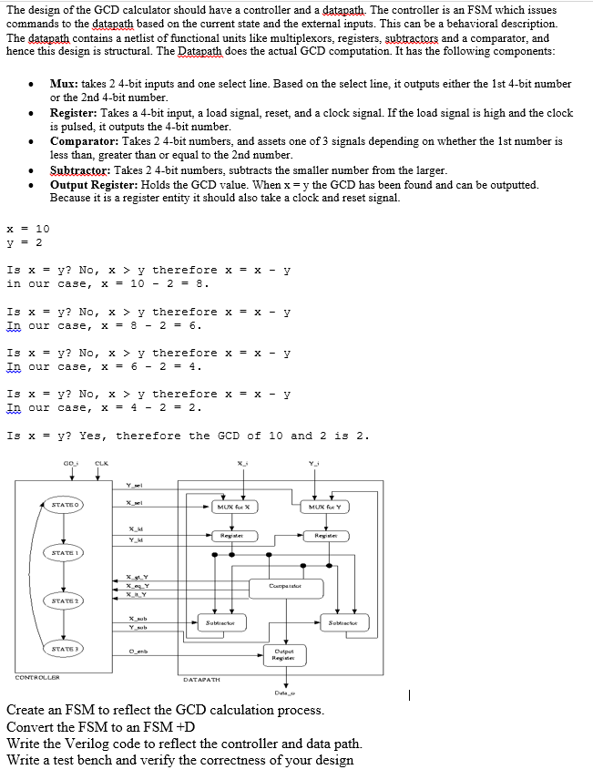
The design of the GCD calculator should have a controller and a datapath. The controller is an FSM which issues commands to the datapath based
The design of the GCD calculator should have a controller and a datapath. The controller is an FSM which issues
commands to the datapath based on the current state and the external inputs. This can be a behavioral description.
The datapath contains a netlist of functional units like multiplexors, registers, subtractors and a comparator, and
hence this design is structural. The Datapath does the actual GCD computation. It has the following components:
Mux: takes bit inputs and one select line. Based on the select line, it outputs either the st bit number
or the nd bit number.
Register: Takes a bit input, a load signal, reset, and a clock signal. If the load signal is high and the clock
is pulsed, it outputs the bit number.
Comparator: Takes bit numbers, and assets one of signals depending on whether the st number is
less than, greater than or equal to the nd number.
Subtractor: Takes bit numbers, subtracts the smaller number from the larger.
Output Register: Holds the GCD value. When the GCD has been found and can be outputted.
Because it is a register entity it should also take a clock and reset signal.
Is No therefore
in our case,
Is No therefore
In our case,
Is No therefore
In our case,
Is No therefore
In our case,
Is Yes, therefore the GCD of and is
Create an FSM to reflect the GCD calculation process.
Convert the FSM to an FSM D
Write the Verilog code to reflect the controller and data path.
Write a test bench and verify the correctness of your design

Step by Step Solution
There are 3 Steps involved in it
Step: 1

Get Instant Access to Expert-Tailored Solutions
See step-by-step solutions with expert insights and AI powered tools for academic success
Step: 2

Step: 3

Ace Your Homework with AI
Get the answers you need in no time with our AI-driven, step-by-step assistance
Get Started


