

Answered step by step
Verified Expert Solution
Question
1 Approved Answer
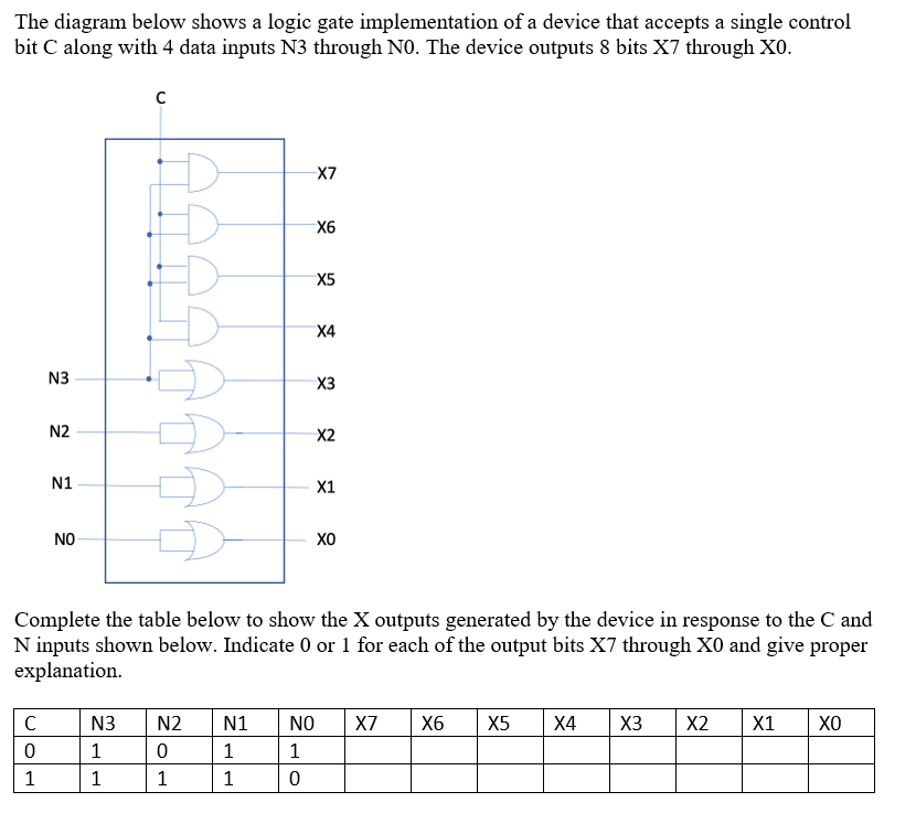
. The diagram below shows a logic gate implementation of a device that accepts a single control bit C along with 4 data inputs N
The diagram below shows a logic gate implementation of a device that accepts a single control
bit along with data inputs through N The device outputs bits through X
Complete the table below to show the outputs generated by the device in response to the and
inputs shown below. Indicate or for each of the output bits through and give proper
explanation.
Step by Step Solution
There are 3 Steps involved in it
Step: 1

Get Instant Access to Expert-Tailored Solutions
See step-by-step solutions with expert insights and AI powered tools for academic success
Step: 2

Step: 3
Ace Your Homework with AI
Get the answers you need in no time with our AI-driven, step-by-step assistance
Get Started
Learning MySQL Get A Handle On Your Data
Authors: Seyed M M Tahaghoghi
1st Edition
0596529465, 9780596529468