Answered step by step
Verified Expert Solution
Question
1 Approved Answer
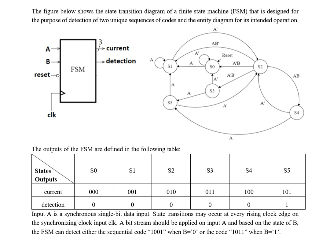
The figure below shows the state transition diagram of a finite state machine ( FSM ) that is designed for the purpose of detection of
The figure below shows the state transition diagram of a finite state machine FSM that is designed for
the purpose of detection of two unique sequences of codes and the entity diagram for its intended operation.
A
The outputs of the FSM are defined in the following table:
Input A is a synchronous singlebit data input. State transitions may occur at every rising clock edge on
the synchronizing clock input clk A bit stream should be applied on input A and based on the state of B
the FSM can detect either the sequential code when or the code when The figure below shows the state transition diagram of a finite state machine FSM that is designed for
the purpose of detection of two unique sequences of codes and the entity diagram for its intended operation.
A
The outputs of the FSM are defined in the following table:
Input A is a synchronous singlebit data input. State transitions may occur at every rising clock edge on
the synchronizing clock input clk A bit stream should be applied on input A and based on the state of B
the FSM can detect either the sequential code when or the code when

Step by Step Solution
There are 3 Steps involved in it
Step: 1

Get Instant Access to Expert-Tailored Solutions
See step-by-step solutions with expert insights and AI powered tools for academic success
Step: 2

Step: 3

Ace Your Homework with AI
Get the answers you need in no time with our AI-driven, step-by-step assistance
Get Started


