

Answered step by step
Verified Expert Solution
Question
1 Approved Answer
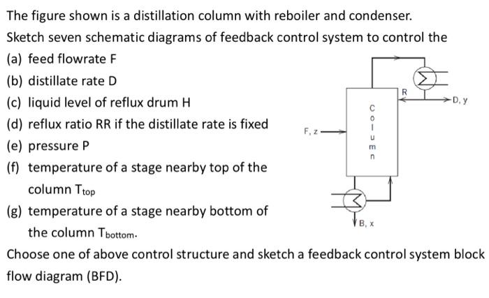
The figure shown is a distillation column with reboiler and condenser. Sketch seven schematic diagrams of feedback control system to control the (a) feed flowrate
Step by Step Solution
There are 3 Steps involved in it
Step: 1

Get Instant Access to Expert-Tailored Solutions
See step-by-step solutions with expert insights and AI powered tools for academic success
Step: 2

Step: 3
Ace Your Homework with AI
Get the answers you need in no time with our AI-driven, step-by-step assistance
Get Started
Inverse Heat Conduction Ill Posed Problems
Authors: Hamidreza Najafi, Keith A. Woodbury, Filippo De Monte, James V. Beck
2nd Edition
1119840198, 978-1119840190