The figure shows the circuitry for a typical display consisting of 7 LEDs arranged in a figure of eight formation. The LEDs (labelled a to
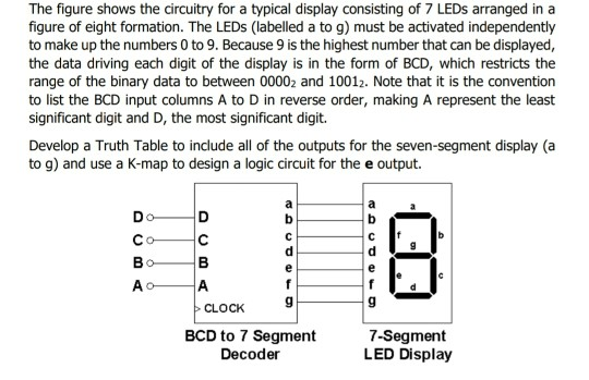
The figure shows the circuitry for a typical display consisting of 7 LEDs arranged in a figure of eight formation. The LEDs (labelled a to g) must be activated independently to make up the numbers 0 to 9. Because 9 is the highest number that can be displayed, the data driving each digit of the display is in the form of BCD, which restricts the range of the binary data to between 00002 and 10012. Note that it is the convention to list the BCD input columns A to D in reverse order, making A represent the least significant digit and D, the most significant digit. Develop a Truth Table to include all of the outputs for the seven-segment display (a to g) and use a K-map to design a logic circuit for the e output.

The figure shows the circuitry for a typical display consisting of 7 LEDs arranged in a figure of eight formation. The LEDs (labelled a to g) must be activated independently to make up the numbers 0 to 9. Because 9 is the highest number that can be displayed, the data driving each digit of the display is in the form of BCD, which restricts the range of the binary data to between 00002 and 10012. Note that it is the convention to list the BCD input columns A to D in reverse order, making A represent the least significant digit and D, the most significant digit. Develop a Truth Table to include all of the outputs for the seven-segment display (a to g) and use a K-map to design a logic circuit for the e output. 6 6 6 6 CLOCK BCD to 7 Segment Decoder 7-Segment LED Display
Step by Step Solution
There are 3 Steps involved in it
Step: 1

Get step-by-step solutions from verified subject matter experts
100% Satisfaction Guaranteed-or Get a Refund!
Step: 2Unlock detailed examples and clear explanations to master concepts

Step: 3Unlock to practice, ask and learn with real-world examples

See step-by-step solutions with expert insights and AI powered tools for academic success
-
 Access 30 Million+ textbook solutions.
-
 Ask unlimited questions from AI Tutors.
-
 Order free textbooks.
-
 100% Satisfaction Guaranteed-or Get a Refund!
Claim Your Hoodie Now!

Study Smart with AI Flashcards
Access a vast library of flashcards, create your own, and experience a game-changing transformation in how you learn and retain knowledge
Explore Flashcards


