Answered step by step
Verified Expert Solution
Link Copied!

Question

1 Approved Answer

The following figure shows a practical implementation of a pulse register. Clock Clk is ideal with a 50% duty cycle. Assume V_DD = 1.2 V,
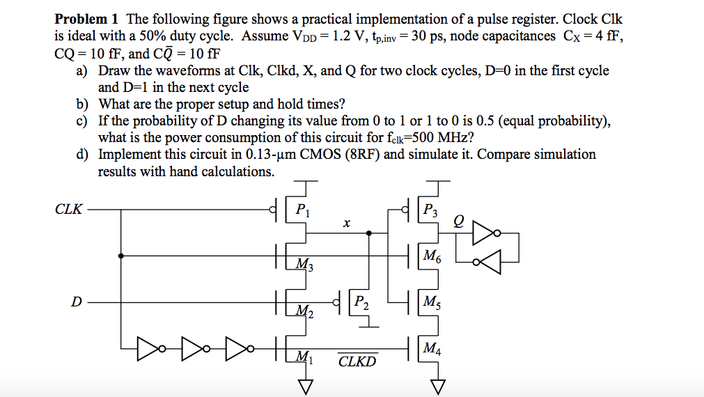
image text in transcribed

The following figure shows a practical implementation of a pulse register. Clock Clk is ideal with a 50% duty cycle. Assume V_DD = 1.2 V, t_p, in v = 30 ps, node capacitances C_x = 4 fF, CQ = 10 fF, and CQ = 10 fF a) Draw the waveforms at Clk, Clkd, X, and Q for two clock cycles, D = 0 in the first cycle and D = 1 in the next cycle b) What are the proper setup and hold times? c) If the probability of D changing its value from 0 to 1 or 1 to 0 is 0.5 (equal probability), what is the power consumption of this circuit for f_clk = 500 MHz? d) Implement this circuit in 0.13- mu m CMOS (8RF) and simulate it. Compare simulation results with hand calculations

Step by Step Solution

There are 3 Steps involved in it

Step: 1

blur-text-image

Get Instant Access to Expert-Tailored Solutions

See step-by-step solutions with expert insights and AI powered tools for academic success

Step: 2

blur-text-image

Step: 3

blur-text-image

Ace Your Homework with AI

Get the answers you need in no time with our AI-driven, step-by-step assistance

Get Started

Recommended Textbook for

More Books

Students also viewed these Databases questions