Answered step by step
Verified Expert Solution
Question
1 Approved Answer
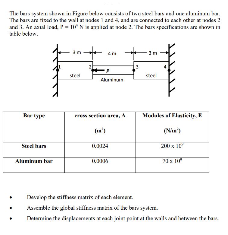
The bars system shown in Figure below consists of two steel bars and one aluminum bar. The bars are fixed to the wall at

The bars system shown in Figure below consists of two steel bars and one aluminum bar. The bars are fixed to the wall at nodes 1 and 4, and are connected to each other at nodes 2 and 3. An axial load, P = 104 N is applied at node 2. The bars specifications are shown in table below. Bar type Steel bars Aluminum bar 3 m steel * 2 4 m P Aluminum cross section area, A (m) 0.0024 0.0006 3 3 m steel Modules of Elasticity, E (N/m) 200 x 10 70 x 10 Develop the stiffness matrix of each element. Assemble the global stiffness matrix of the bars system. Determine the displacements at each joint point at the walls and between the bars.
Step by Step Solution
There are 3 Steps involved in it
Step: 1

Get Instant Access to Expert-Tailored Solutions
See step-by-step solutions with expert insights and AI powered tools for academic success
Step: 2

Step: 3

Ace Your Homework with AI
Get the answers you need in no time with our AI-driven, step-by-step assistance
Get Started


