Answered step by step
Verified Expert Solution
Question
1 Approved Answer
the impedence values in question 4 is j0.25 and the reactance is 0.5 10 10 6 1. For the system data given below draw the


the impedence values in question 4 is j0.25
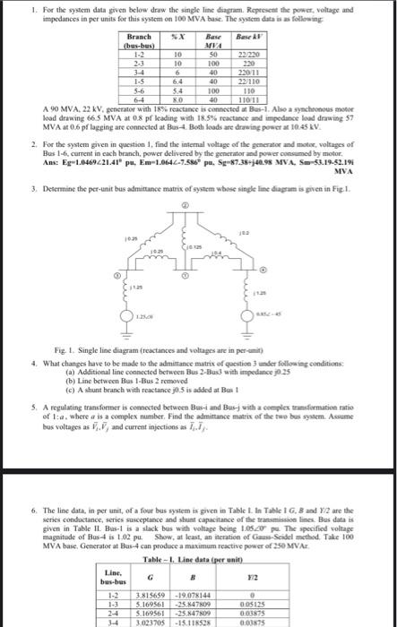
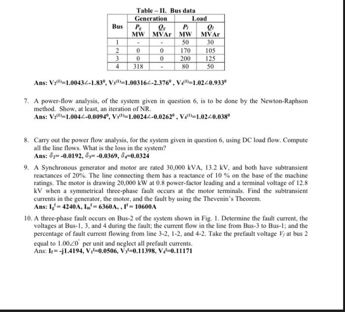
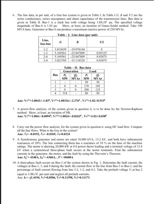
10 10 6 1. For the system data given below draw the single line diagram. Represent the power, voltage and impedances in per units for this system on 100 MVA base. The system data is as following Branch Bar Base Ar bus-bus) MA 50 23220 100 220 40 2011 1-5 6.4 40 22110 5-6 5.4 100 110 6-4 X0 40 110 11 A 90 MVA, 22 kV. generator with 18% reactance is connected at Bus-1. Also a synchronous motor load drawing 66.5 MVA at 0.8 pf leading with 18.5% ractance and impedance load drawing 57 MVA at 0.6 pflagging are connected at Bush Both loads are drawing power at 10:45 KV. 2. For the system given in question 1 find the internal voltage of the generator and mater, voltages of Bus 1.6. current in cach branch, power delivered by the generator and power consumed by motor Ans: Eg-1.0469421.41pu Em-1.0642-7.586 pu. Se 87.38-40.98 MVA, S-53.19-52.19 MVA 3. Determine the per-unit bus admittance matrix of system whose single line diagram is given in Fig I. 10. Fig. 1. Single line diagram (teactances and voltages are in perc) 4. What changes lave to be made to the admittance matrix of question under following conditions (a) Additional line connected between Bus 2-Bus with impedance 25 b) Line between Bas 1-Bus 2 removed (c) A shunt branch with reactance j05 is added at Bos : 5. A regulating transformer is connected between Bus-Land Busy with complex transformation ratio of 1:a, where is a complex number. Find the admittance matrix of the two bus system. Assume bus voltages as 1,7, and current injections 17) 6. The line data, in per unit of a four bus system is given in Table 1. In Table 1 G. Band Y.2 are the series conductance, series susceptance and sunt capacitance of the transmission lines Bas data given in Table II Bus is a slack bus with voltage being 1.05.20 pe The specified voltage magnitude of Bus4 is 102 pu. Show, at least, an iteration of GaussScadel method. Take 100 MVA base. Generator at Bus-4 can produce a maximum active power of 250 MVA Table - Line data (per unit) Line. bus-bes 1-2 3.81 5659 -19.078144 5.169561 -25.847809 0.05125 S.169561 -25.84709 001 3-4 3.023705 -15.118$25 0.03575 Bus Table - II. Bus data Generation Load . P MW MVAr MW MVA 50 30 0 170 105 0 0 200 125 318 80 50 1 2 3 4 Ans: V:(=1.00434-1.83", Vy(1=1.003162-2.376", V40=1.0220.9330 7. A power-flow analysis, of the system given in question 6, is to be done by the Newton-Raphson method. Show, at least, an iteration of NR. Ans: V:(0)=1.0042-0.0094", V:(-1.00242-0.0262", V."=1.0240.038" 8. Carry out the power flow analysis, for the system given in question 6, using DC load flow. Compute all the line flows. What is the loss in the system? Ans: 8=-0.0192, 8=-0.0369, 8-0.0324 9. A Synchronous generator and motor are rated 30,000 kVA, 13.2 kV, and both have subtransient reactances of 20%. The line connecting them has a reactance of 10 % on the base of the machine ratings. The motor is drawing 20,000 kW at 0.8 power-factor leading and a terminal voltage of 12.8 kV when a symmetrical three-phase fault occurs at the motor terminals. Find the subtransient currents in the generator, the motor, and the fault by using the Thevenin's Theorem. Ans: 1-4240A, 1.-6360A, 1'- 10600A 10. A three-phase fault occurs on Bus-2 of the system shown in Fig. 1. Determine the fault current, the voltages at Bus-1, 3, and 4 during the fault; the current flow in the line from Bus-3 to Bus-l; and the percentage of fault current flowing from line 3-2, 1-2, and 4-2. Take the prefault voltage Vyat bus 2 equal to 1.0020 per unit and neglect all prefault currents. Ans: 1-j1.4194, V,'-0.0506, VP=0.11398, V4=0.11171 6. The line data, in per unit of a four bus system is given in Table L. In Table 1 G, B and Y/2 are the series conductance, series susceptance and shunt capacitance of the transmission lines. Bus data is given in Table 11. Bus-1 is a slack bus with voltage being 1.0520 pu. The specified voltage magnitude of Bus-4 is 1.02 pu. Show, at least, an iteration of Gauss-Seidel method. Take 100 MVA buse. Generator at Bus-4 can produce a maximum reactive power of 250 MVAr. Table - 1. Line data (per unit) Line. B G bus-bus 1-2 1-3 3.815659 -19,078144 5.169561 -25.847809 5.169561 -25.847809 3.023705 - 15.118528 0 0.05125 0.03875 0.03875 3-4 Bus Table -II. Bus data Generation Load P. P MW MVAr MW MVAr - 50 30 0 0 170 105 0 0 200 125 318 80 50 1 2 3 4 Ans: Vall -1.00434-1.83", V-1.003162-2.376", V-1.0240.933" 7. A power-flow analysis, of the system given in question 6, is to be done by the Newton-Raphson Ans: Vz'fl-1.0042-0.0094", V-1.00242-0.0262. Ve=1.0220.038 8. Carry out the power flow analysis, for the system given in question 6, using DC load flow. Compute all the line flows. What is the loss in the system? Ans: 8-0.0192, 8--0.0369,6--0.0324 9. A Synchronous generator and motor are rated 30,000 KVA, 13.2 kV, and both have subtransient reactances of 20%. The line connecting them has a reactance of 10% on the base of the machine ratings. The motor is drawing 20,000 kW at 0.8 power-factor leading and a terminal voltage of 12.8 kV when a symmetrical three-phase fault occurs at the motor terminals. Find the subtransient currents in the generator, the motor, and the fault by using the Thevenin's Theorem. Ans: 1' = 4240A, 1.'=6360A, l'=10600A 10. A three-phase fault occurs on Bus-2 of the system shown in Fig. 1. Determine the fault current, the voltages at Bus-1.3, and 4 during the fault: the current flow in the line from Bus-3 to Bus-l: and the percentage of fault current flowing from line 3-2, 1-2, and 4-2. Take the prefault voltage V, at bus 2 equal to 1.0020 per unit and neglect all prefault currents. Ans: 1-j1.4194, V-0.0506, V-0.11398, V10.11171 10 10 6 1. For the system data given below draw the single line diagram. Represent the power, voltage and impedances in per units for this system on 100 MVA base. The system data is as following Branch Bar Base Ar bus-bus) MA 50 23220 100 220 40 2011 1-5 6.4 40 22110 5-6 5.4 100 110 6-4 X0 40 110 11 A 90 MVA, 22 kV. generator with 18% reactance is connected at Bus-1. Also a synchronous motor load drawing 66.5 MVA at 0.8 pf leading with 18.5% ractance and impedance load drawing 57 MVA at 0.6 pflagging are connected at Bush Both loads are drawing power at 10:45 KV. 2. For the system given in question 1 find the internal voltage of the generator and mater, voltages of Bus 1.6. current in cach branch, power delivered by the generator and power consumed by motor Ans: Eg-1.0469421.41pu Em-1.0642-7.586 pu. Se 87.38-40.98 MVA, S-53.19-52.19 MVA 3. Determine the per-unit bus admittance matrix of system whose single line diagram is given in Fig I. 10. Fig. 1. Single line diagram (teactances and voltages are in perc) 4. What changes lave to be made to the admittance matrix of question under following conditions (a) Additional line connected between Bus 2-Bus with impedance 25 b) Line between Bas 1-Bus 2 removed (c) A shunt branch with reactance j05 is added at Bos : 5. A regulating transformer is connected between Bus-Land Busy with complex transformation ratio of 1:a, where is a complex number. Find the admittance matrix of the two bus system. Assume bus voltages as 1,7, and current injections 17) 6. The line data, in per unit of a four bus system is given in Table 1. In Table 1 G. Band Y.2 are the series conductance, series susceptance and sunt capacitance of the transmission lines Bas data given in Table II Bus is a slack bus with voltage being 1.05.20 pe The specified voltage magnitude of Bus4 is 102 pu. Show, at least, an iteration of GaussScadel method. Take 100 MVA base. Generator at Bus-4 can produce a maximum active power of 250 MVA Table - Line data (per unit) Line. bus-bes 1-2 3.81 5659 -19.078144 5.169561 -25.847809 0.05125 S.169561 -25.84709 001 3-4 3.023705 -15.118$25 0.03575 Bus Table - II. Bus data Generation Load . P MW MVAr MW MVA 50 30 0 170 105 0 0 200 125 318 80 50 1 2 3 4 Ans: V:(=1.00434-1.83", Vy(1=1.003162-2.376", V40=1.0220.9330 7. A power-flow analysis, of the system given in question 6, is to be done by the Newton-Raphson method. Show, at least, an iteration of NR. Ans: V:(0)=1.0042-0.0094", V:(-1.00242-0.0262", V."=1.0240.038" 8. Carry out the power flow analysis, for the system given in question 6, using DC load flow. Compute all the line flows. What is the loss in the system? Ans: 8=-0.0192, 8=-0.0369, 8-0.0324 9. A Synchronous generator and motor are rated 30,000 kVA, 13.2 kV, and both have subtransient reactances of 20%. The line connecting them has a reactance of 10 % on the base of the machine ratings. The motor is drawing 20,000 kW at 0.8 power-factor leading and a terminal voltage of 12.8 kV when a symmetrical three-phase fault occurs at the motor terminals. Find the subtransient currents in the generator, the motor, and the fault by using the Thevenin's Theorem. Ans: 1-4240A, 1.-6360A, 1'- 10600A 10. A three-phase fault occurs on Bus-2 of the system shown in Fig. 1. Determine the fault current, the voltages at Bus-1, 3, and 4 during the fault; the current flow in the line from Bus-3 to Bus-l; and the percentage of fault current flowing from line 3-2, 1-2, and 4-2. Take the prefault voltage Vyat bus 2 equal to 1.0020 per unit and neglect all prefault currents. Ans: 1-j1.4194, V,'-0.0506, VP=0.11398, V4=0.11171 6. The line data, in per unit of a four bus system is given in Table L. In Table 1 G, B and Y/2 are the series conductance, series susceptance and shunt capacitance of the transmission lines. Bus data is given in Table 11. Bus-1 is a slack bus with voltage being 1.0520 pu. The specified voltage magnitude of Bus-4 is 1.02 pu. Show, at least, an iteration of Gauss-Seidel method. Take 100 MVA buse. Generator at Bus-4 can produce a maximum reactive power of 250 MVAr. Table - 1. Line data (per unit) Line. B G bus-bus 1-2 1-3 3.815659 -19,078144 5.169561 -25.847809 5.169561 -25.847809 3.023705 - 15.118528 0 0.05125 0.03875 0.03875 3-4 Bus Table -II. Bus data Generation Load P. P MW MVAr MW MVAr - 50 30 0 0 170 105 0 0 200 125 318 80 50 1 2 3 4 Ans: Vall -1.00434-1.83", V-1.003162-2.376", V-1.0240.933" 7. A power-flow analysis, of the system given in question 6, is to be done by the Newton-Raphson Ans: Vz'fl-1.0042-0.0094", V-1.00242-0.0262. Ve=1.0220.038 8. Carry out the power flow analysis, for the system given in question 6, using DC load flow. Compute all the line flows. What is the loss in the system? Ans: 8-0.0192, 8--0.0369,6--0.0324 9. A Synchronous generator and motor are rated 30,000 KVA, 13.2 kV, and both have subtransient reactances of 20%. The line connecting them has a reactance of 10% on the base of the machine ratings. The motor is drawing 20,000 kW at 0.8 power-factor leading and a terminal voltage of 12.8 kV when a symmetrical three-phase fault occurs at the motor terminals. Find the subtransient currents in the generator, the motor, and the fault by using the Thevenin's Theorem. Ans: 1' = 4240A, 1.'=6360A, l'=10600A 10. A three-phase fault occurs on Bus-2 of the system shown in Fig. 1. Determine the fault current, the voltages at Bus-1.3, and 4 during the fault: the current flow in the line from Bus-3 to Bus-l: and the percentage of fault current flowing from line 3-2, 1-2, and 4-2. Take the prefault voltage V, at bus 2 equal to 1.0020 per unit and neglect all prefault currents. Ans: 1-j1.4194, V-0.0506, V-0.11398, V10.11171 and the reactance is 0.5
Step by Step Solution
There are 3 Steps involved in it
Step: 1

Get Instant Access to Expert-Tailored Solutions
See step-by-step solutions with expert insights and AI powered tools for academic success
Step: 2

Step: 3

Ace Your Homework with AI
Get the answers you need in no time with our AI-driven, step-by-step assistance
Get Started


