Answered step by step
Verified Expert Solution
Question
1 Approved Answer
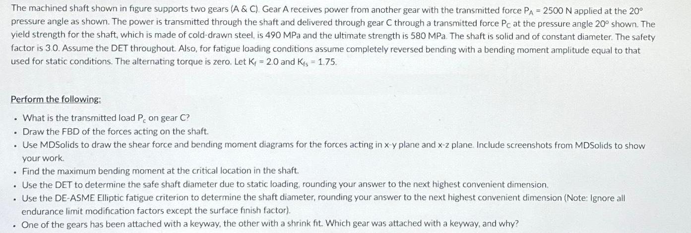
The machined shaft shown in figure supports two gears (A & C) Gear A receives power from another gear with the transmitted force PA


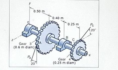
The machined shaft shown in figure supports two gears (A & C) Gear A receives power from another gear with the transmitted force PA = 2500 N applied at the 20 pressure angle as shown. The power is transmitted through the shaft and delivered through gear C through a transmitted force Pc at the pressure angle 200 shown. The yield strength for the shaft, which is made of cold-drawn steel, is 490 MPa and the ultimate strength is 580 MPa. The shaft is solid and of constant diameter. The safety factor is 3.0. Assume the DET throughout. Also, for fatigue loading conditions assume completely reversed bending with a bending moment amplitude equal to that used for static conditions. The alternating torque is zero. Let K = 2.0 and Kfs = 1.75. Perform the following: . What is the transmitted load P. on gear C? . Draw the FBD of the forces acting on the shaft. Use MDSolids to draw the shear force and bending moment diagrams for the forces acting in x-y plane and x-z plane. Include screenshots from MDSolids to show your work. . Find the maximum bending moment at the critical location in the shaft. . Use the DET to determine the safe shaft diameter due to static loading, rounding your answer to the next highest convenient dimension. . Use the DE-ASME Elliptic fatigue criterion to determine the shaft diameter, rounding your answer to the next highest convenient dimension (Note: Ignore all endurance limit modification factors except the surface finish factor). . One of the gears has been attached with a keyway, the other with a shrink fit. Which gear was attached with a keyway, and why? 0.50 m Gear 3 (0.6 m diam)) PA 20 0.40 m 0.25 m B Gear 4 (0.25 m diam) Pc 20 X
Step by Step Solution
There are 3 Steps involved in it
Step: 1
The question youve provided involves determining various mechanical characteristics of a shaft that is part of a gear system Unfortunately without access to MDSolids software I cannot create the shear ...
Get Instant Access to Expert-Tailored Solutions
See step-by-step solutions with expert insights and AI powered tools for academic success
Step: 2

Step: 3

Ace Your Homework with AI
Get the answers you need in no time with our AI-driven, step-by-step assistance
Get Started


