Question
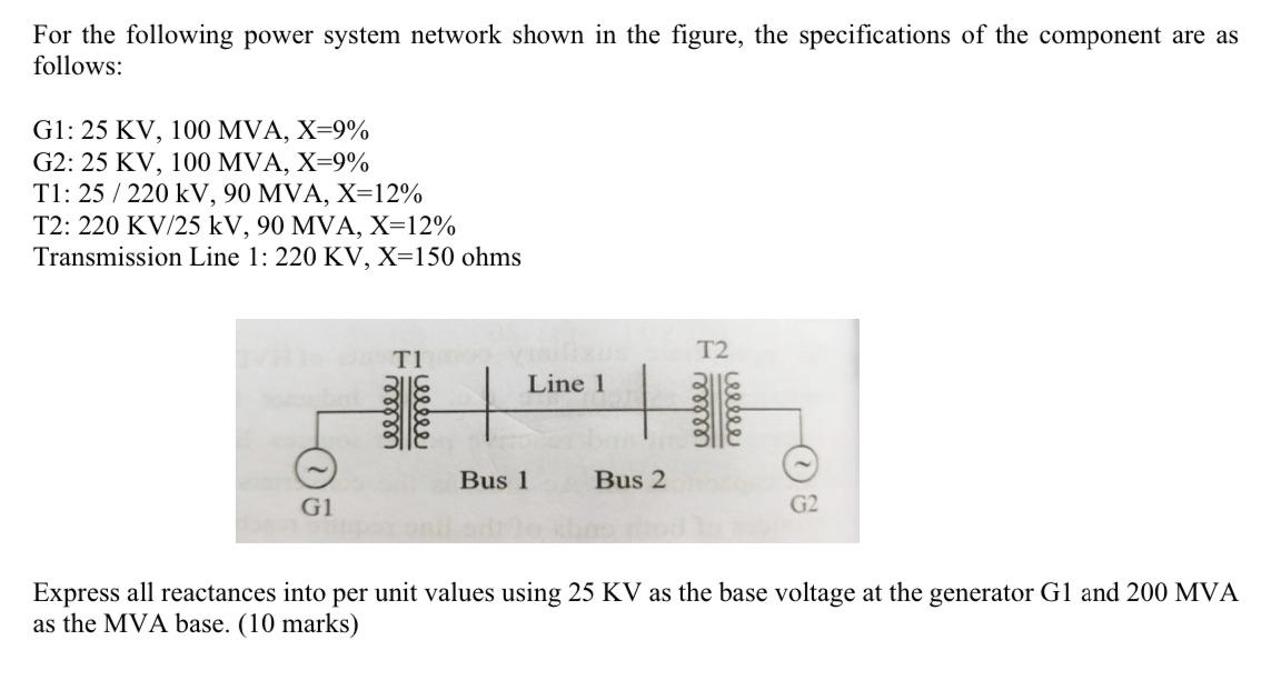
For the following power system network shown in the figure, the specifications of the component are as follows: G1: 25 KV, 100 MVA, X-9%

For the following power system network shown in the figure, the specifications of the component are as follows: G1: 25 KV, 100 MVA, X-9% G2: 25 KV, 100 MVA, X=9% T1: 25/220 kV, 90 MVA, X=12% T2: 220 KV/25 kV, 90 MVA, X=12% Transmission Line 1: 220 KV, X=150 ohms noterbat G1 T1 Line 1 Bus 1 + Bus 2 T2 cellee Express all reactances into per unit values using 25 KV as the base voltage at the generator G1 and 200 MVA as the MVA base. (10 marks)
Step by Step Solution
There are 3 Steps involved in it
Step: 1

Get Instant Access to Expert-Tailored Solutions
See step-by-step solutions with expert insights and AI powered tools for academic success
Step: 2

Step: 3

Ace Your Homework with AI
Get the answers you need in no time with our AI-driven, step-by-step assistance
Get StartedRecommended Textbook for
Holt McDougal Larson Geometry
Authors: Ron Larson, Laurie Boswell, Timothy D. Kanold, Lee Stiff
1st Edition
0547315171, 978-0547315171
Students also viewed these General Management questions
Question
Answered: 1 week ago
Question
Answered: 1 week ago
Question
Answered: 1 week ago
Question
Answered: 1 week ago
Question
Answered: 1 week ago
Question
Answered: 1 week ago
Question
Answered: 1 week ago
Question
Answered: 1 week ago
Question
Answered: 1 week ago
Question
Answered: 1 week ago
Question
Answered: 1 week ago
Question
Answered: 1 week ago
Question
Answered: 1 week ago
Question
Answered: 1 week ago
Question
Answered: 1 week ago
Question
Answered: 1 week ago
Question
Answered: 1 week ago
View Answer in SolutionInn App


