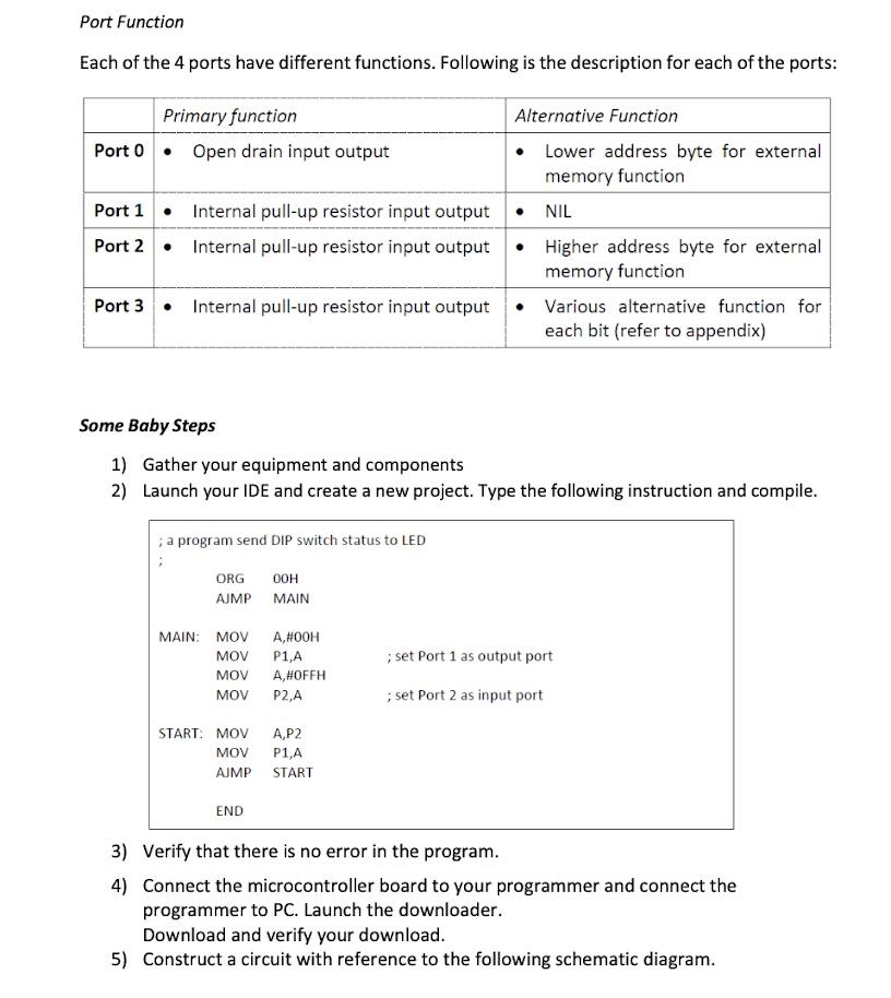
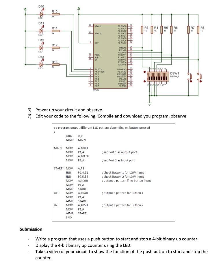
The Needy Checklist You will need the following equipment for this lab session: Digital Power Supply Breadboard Jumper wires Computer with assembler/IDE 8051 breakout board 8051 programmer You should have the following components: LED x4 DIP switch 8-ways x1 Tactile switch x2 Resistor 1000 ohm X10 Good to Know Background The 8051 I/O Port 8051 microcontrollers have 4 1/0 ports with 8-bit each. Each of the bit, which is made up of a pin on the microcontroller can be configured as input or output. Hence, there is a total of 32 pins of 1/O available with the 8051 microcontroller. As each of the I/O pins can be either an input or an output, configuration is required to tell the microcontroller how the pin should function. Writing a logic zero (0) to the port bit will configure the pin to an output pin. Similarly, writing a logic one (1) to the port bit will configure the relevant pin into an input pin. Being an 1/0 port, the current for each of the port is limited. Being an output port, each port is limited to receiving 10mA of current and a maximum of 15mA if all 8-bits are active. Should all ports and pins are active, the total current is limited to only 71mA. Excessive current may damage your microcontroller. Port Function Each of the 4 ports have different functions. Following is the description for each of the ports: Primary function Alternative Function Port 0 Open drain input output Lower address byte for external memory function Port 1 Internal pull-up resistor input output NIL Port 2 Internal pull-up resistor input output Higher address byte for external memory function Port 3. Internal pull-up resistor input output Various alternative function for each bit (refer to appendix) Some Baby Steps 1) Gather your equipment and components 2) Launch your IDE and create a new project. Type the following instruction and compile. ; a program send DIP switch status to LED ORG OOH AJMP MAIN MAIN: MOV MOV MOV MOV A,#OOH P1,A A,#OFFH P2,A ; set Port 1 as output port set Port 2 as input port START: MOV MOV AJMP A,P2 P1,A START END 3) Verify that there is no error in the program. 4) Connect the microcontroller board to your programmer and connect the programmer to PC. Launch the downloader. Download and verify your download. 5) Construct a circuit with reference to the following schematic diagram. D10 A R10 13 LED D11 19 XTALS R11 R3 TK R4 SK R5 1 R6 Tk R7 1 R8 XTAR LED D12 RST R12 PO OIADO POSIADT PO ZADO POMADO POGADA POSIADS PO GADS POWIAD P2 P2 TAD P2 A10 P2 A11 P2 A12 P2SA13 PHI V P2TA15 LED 013 FRP EA R13 22 TR LED P10T P11/2EX P12 P13 P14 P15 PUS DSW1 DIPSW_o PORXD 3. TXD PANTO PS INTI P3 4/TO Pa 5/1 PW PSID 17 6) Power up your circuit and observe. 7) Edit your code to the following. Compile and download you program, observe. ; a program output different LED pattern depending on button pressed ORG AJMP MAIN MAIN: MOV MOV MOV MOV ANOOH P1,A A,#OFFH P2,A set Port 1 as output port set Port 2 as input port START: MOV check Button 1 for LOW input check Button 2 for LOW input output a pattern if no button input A,P2 P2.4,81 P2.5,82 A,#OOH P1A START P1A START A,#05H P1,A START JNB JNB MOV MOV AJMP MOV MOV AJMP MOV MOV AJMP END B1: output a pattern for Button 1 B2: ; output a pattern for Button 2 Submission Write a program that uses a push button to start and stop a 4-bit binary up counter. Display the 4-bit binary up counter using the LED. Take a video of your circuit to show the function of the push button to start and stop the counter The Needy Checklist You will need the following equipment for this lab session: Digital Power Supply Breadboard Jumper wires Computer with assembler/IDE 8051 breakout board 8051 programmer You should have the following components: LED x4 DIP switch 8-ways x1 Tactile switch x2 Resistor 1000 ohm X10 Good to Know Background The 8051 I/O Port 8051 microcontrollers have 4 1/0 ports with 8-bit each. Each of the bit, which is made up of a pin on the microcontroller can be configured as input or output. Hence, there is a total of 32 pins of 1/O available with the 8051 microcontroller. As each of the I/O pins can be either an input or an output, configuration is required to tell the microcontroller how the pin should function. Writing a logic zero (0) to the port bit will configure the pin to an output pin. Similarly, writing a logic one (1) to the port bit will configure the relevant pin into an input pin. Being an 1/0 port, the current for each of the port is limited. Being an output port, each port is limited to receiving 10mA of current and a maximum of 15mA if all 8-bits are active. Should all ports and pins are active, the total current is limited to only 71mA. Excessive current may damage your microcontroller. Port Function Each of the 4 ports have different functions. Following is the description for each of the ports: Primary function Alternative Function Port 0 Open drain input output Lower address byte for external memory function Port 1 Internal pull-up resistor input output NIL Port 2 Internal pull-up resistor input output Higher address byte for external memory function Port 3. Internal pull-up resistor input output Various alternative function for each bit (refer to appendix) Some Baby Steps 1) Gather your equipment and components 2) Launch your IDE and create a new project. Type the following instruction and compile. ; a program send DIP switch status to LED ORG OOH AJMP MAIN MAIN: MOV MOV MOV MOV A,#OOH P1,A A,#OFFH P2,A ; set Port 1 as output port set Port 2 as input port START: MOV MOV AJMP A,P2 P1,A START END 3) Verify that there is no error in the program. 4) Connect the microcontroller board to your programmer and connect the programmer to PC. Launch the downloader. Download and verify your download. 5) Construct a circuit with reference to the following schematic diagram. D10 A R10 13 LED D11 19 XTALS R11 R3 TK R4 SK R5 1 R6 Tk R7 1 R8 XTAR LED D12 RST R12 PO OIADO POSIADT PO ZADO POMADO POGADA POSIADS PO GADS POWIAD P2 P2 TAD P2 A10 P2 A11 P2 A12 P2SA13 PHI V P2TA15 LED 013 FRP EA R13 22 TR LED P10T P11/2EX P12 P13 P14 P15 PUS DSW1 DIPSW_o PORXD 3. TXD PANTO PS INTI P3 4/TO Pa 5/1 PW PSID 17 6) Power up your circuit and observe. 7) Edit your code to the following. Compile and download you program, observe. ; a program output different LED pattern depending on button pressed ORG AJMP MAIN MAIN: MOV MOV MOV MOV ANOOH P1,A A,#OFFH P2,A set Port 1 as output port set Port 2 as input port START: MOV check Button 1 for LOW input check Button 2 for LOW input output a pattern if no button input A,P2 P2.4,81 P2.5,82 A,#OOH P1A START P1A START A,#05H P1,A START JNB JNB MOV MOV AJMP MOV MOV AJMP MOV MOV AJMP END B1: output a pattern for Button 1 B2: ; output a pattern for Button 2 Submission Write a program that uses a push button to start and stop a 4-bit binary up counter. Display the 4-bit binary up counter using the LED. Take a video of your circuit to show the function of the push button to start and stop the counter