Question
The phase of the potential difference across an ideal inductor An inductor usually takes the form of a coil of wire with many loops. When
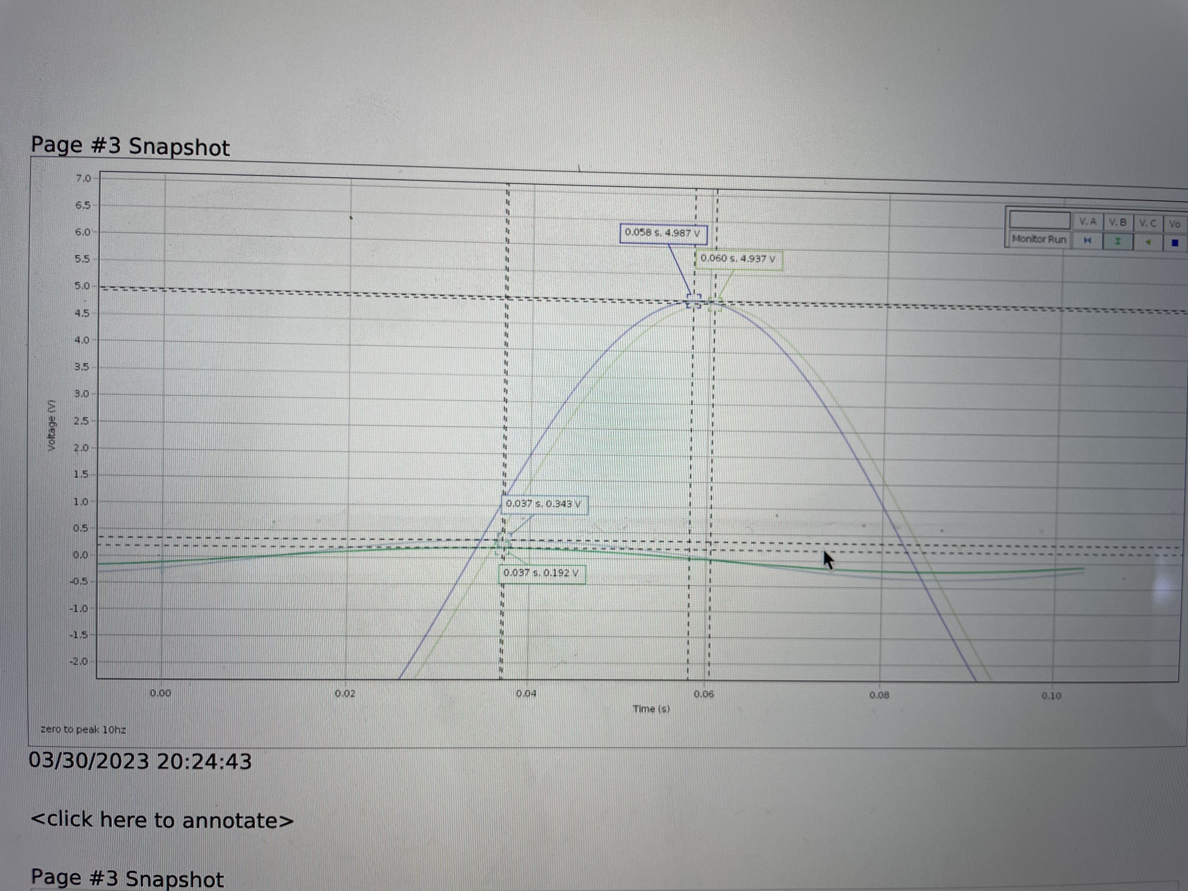
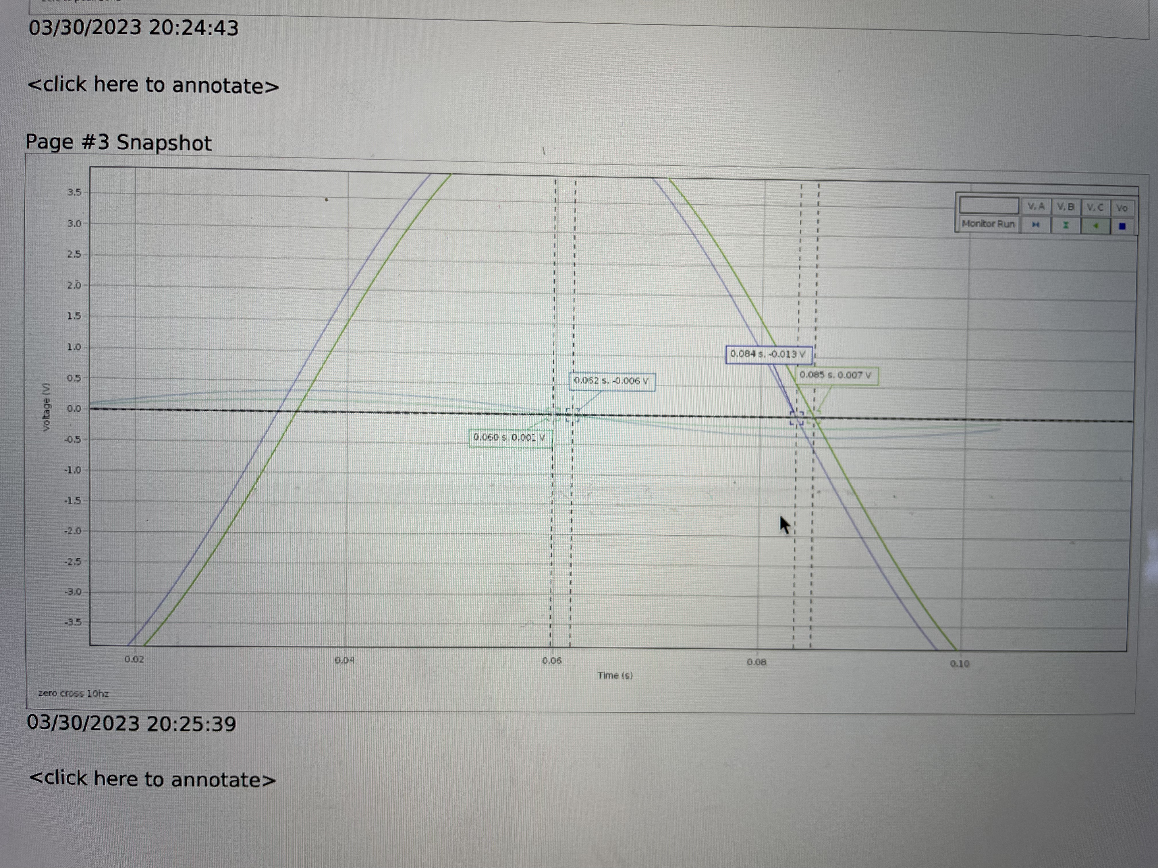
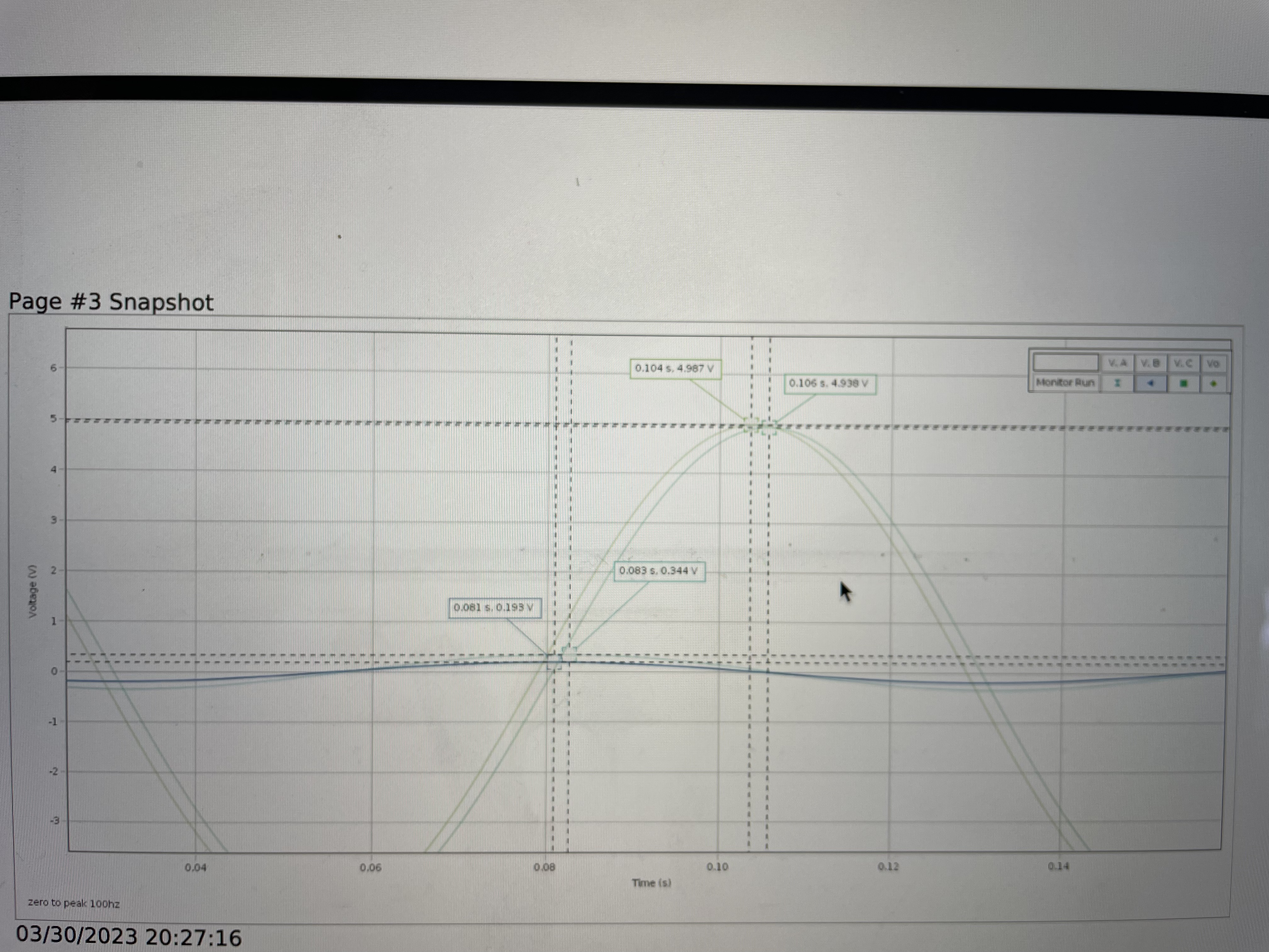
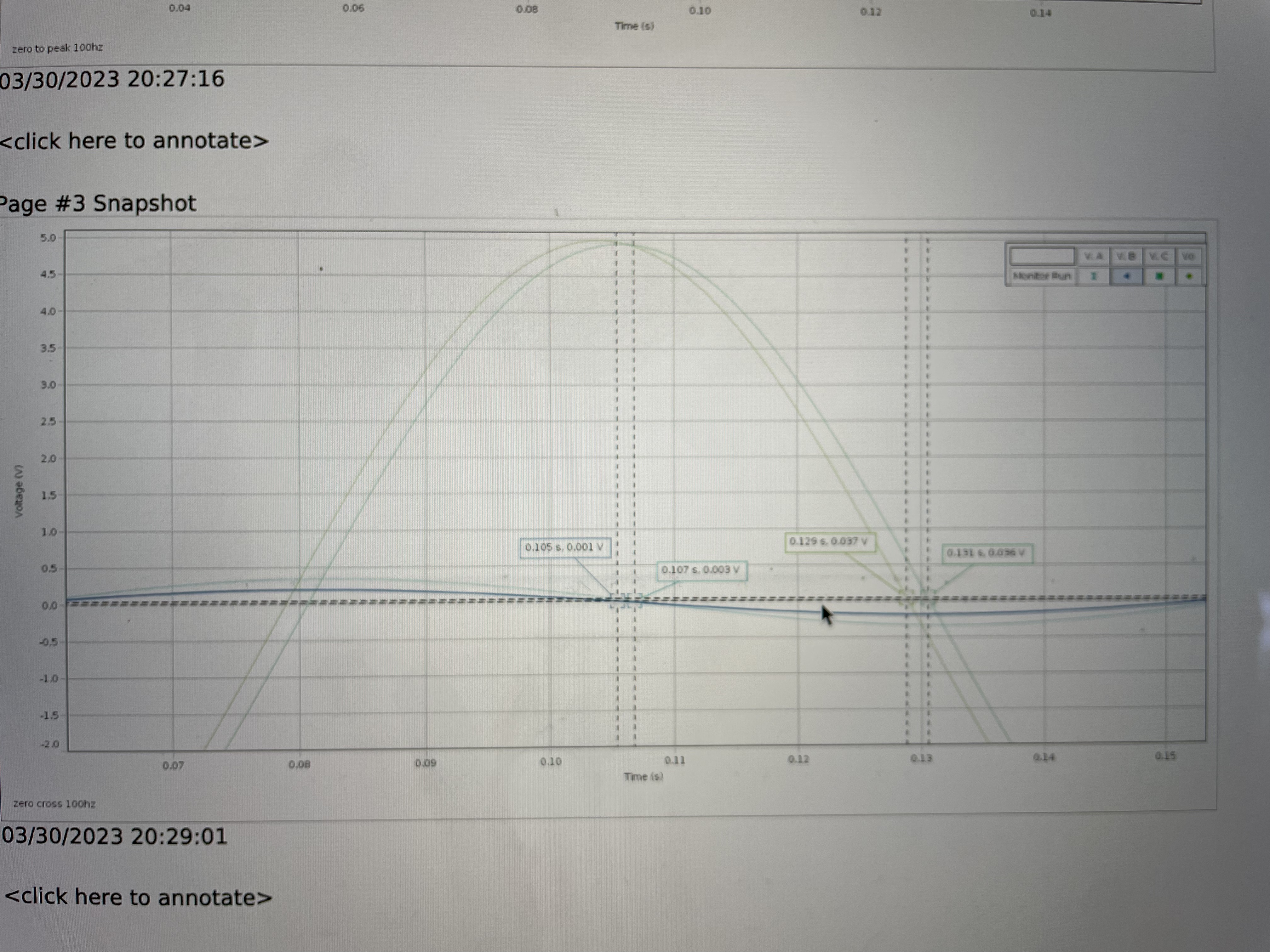
The phase of the potential difference across an ideal inductor An inductor usually takes the form of a coil of wire with many loops. When a time-varying electrical current passes through the loops, the resulting time-varying magnetic field induces a voltage in the coil. According to Lenz's law (and energy conservation) this induced voltage opposes the source voltage, making the current small. When sinusoidally driven, the voltage across and ideal inductor peaks one-fourth of an oscillation period before the current peaks. That is, the voltage "leads" the current by 90 in an ideal inductor. We say that the voltage experiences a +90 phase shift relative to the current in an ideal inductor. This relationship is illustrated in Figure 10.2, where the voltage across Chapter 10. AC Circuits 59 the inductor, VL, peaks 0.25 s (one-fourth of a cycle) before the peak in VR. Again, the sign is chosen so that if I and VR are proportion to cos(?t), VL is proportional to cos(?t +?), where ? = +90.
Recall that in the conductor accumulation of charge means that current flow is initially unimpeded, but resistance to current increases as charge accumulates. For an Inductor, there is initially no magnetic field and so no induced potential, but as the current increases, so does the magnetic field. This results in an increasing emf generation, reducing the potential on the line for other components in the circuit.
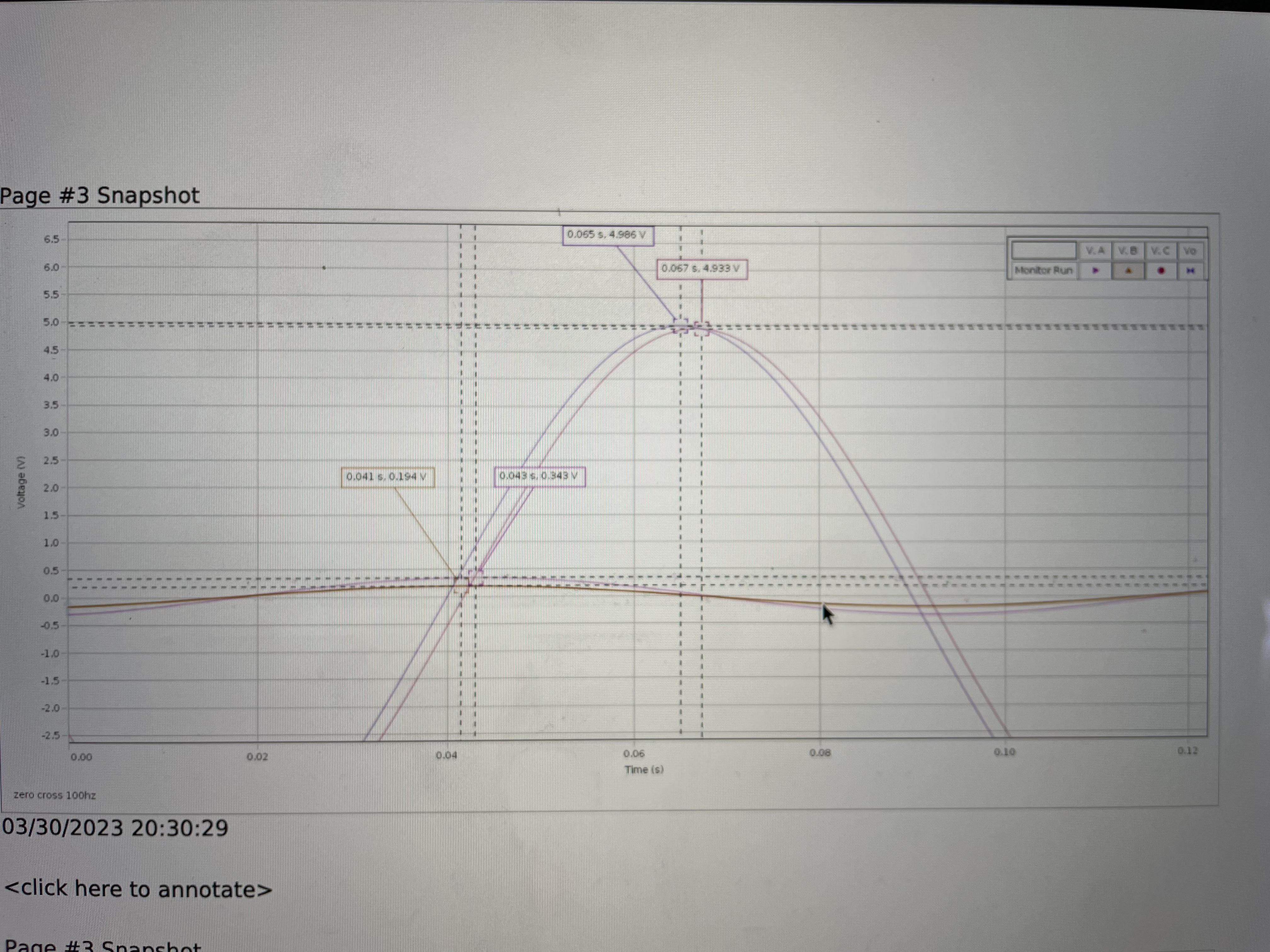
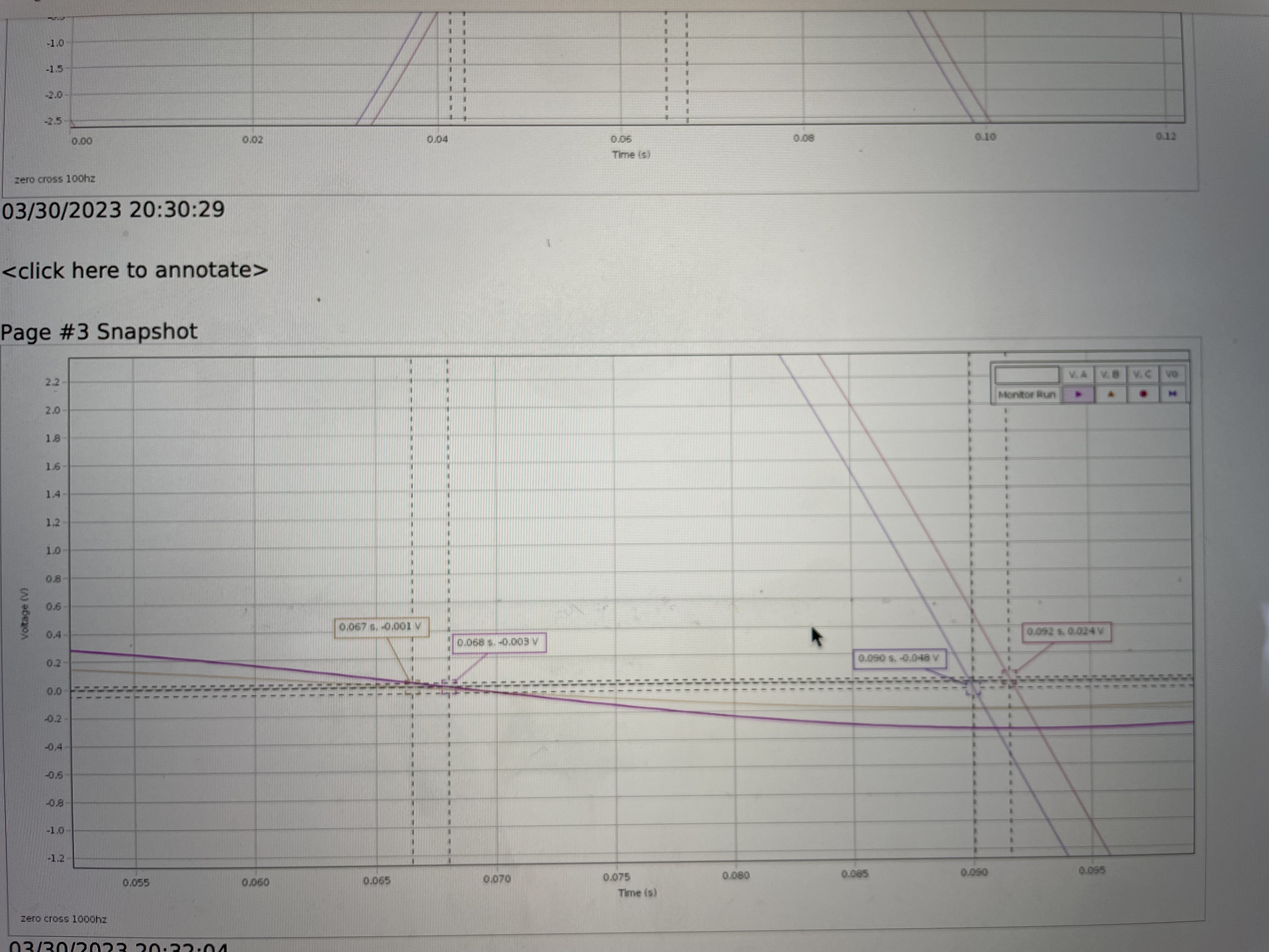
In practice, it is difficult to determine the position of the peak in a sinusoidal signal precisely, because voltage changes slowly near the peak. Measuring the time at which the voltage crosses zero, where the voltage changes rapidly, gives more precise results. Because the voltage crosses zero twice per cycle, it is important to be consistent about which zero crossing is used. The arrows in Figure 10.2 on the previous page show the zero crossings for VL, VR, and VC where the voltage is falling, that is, where the voltage crosses zero from above.
To derive an equation for the phase angle ? for a given voltage signal, one observed that 360 of phase corresponds to one oscillation period T
, ? = [t(VR = 0?)?t(V = 0?)]360 T (10.3)
The order of terms in Equation (10.3) is chosen so that a voltage signal that lags VR has a negative phase, as required by the sine and cosine functions
need help with solving for the phase of each one
Step by Step Solution
There are 3 Steps involved in it
Step: 1

Get Instant Access to Expert-Tailored Solutions
See step-by-step solutions with expert insights and AI powered tools for academic success
Step: 2

Step: 3

Ace Your Homework with AI
Get the answers you need in no time with our AI-driven, step-by-step assistance
Get Started


