Answered step by step
Verified Expert Solution
Question
1 Approved Answer
The primary goal of this laboratory exercise is to gain hands - on experience in configuring and using DMA to transfer data between peripheral modules
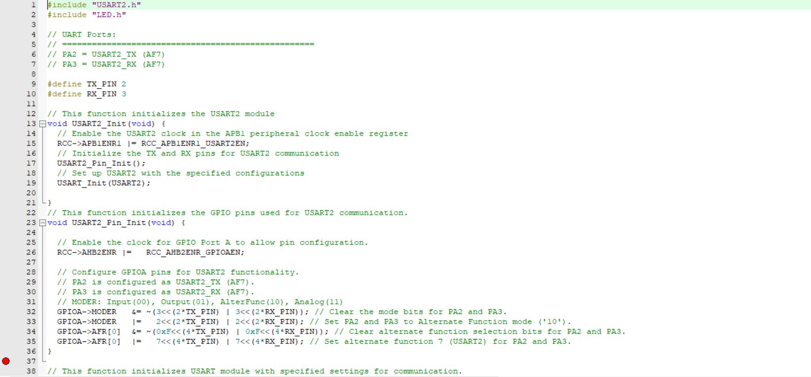
The primary goal of this laboratory exercise is to gain handson experience in configuring and using DMA to transfer data between peripheral modules and memory. Additionally, you will explore essential practices in managing C projects, which involve multiple c and h files. This knowledge is crucial for ensuring the system's maintainability and scalability, as well as for supporting effective collaboration. You are provided with a sample project, LabProjectTemplate, which integrates the Lab project and the UARTTerminal sample project. This project implements a counter that increments by one every second using the generalpurpose timer TIM in output compare toggle mode. The counter value is converted into a character string stored in a character array named 'string, and displayed on a PC serial terminal through the USART TX port. Essentially, you will see the counter value automatically increment by one and be displayed on the serial terminal every second. In this sample project, the character string representing the counter value is transferred from the memory array 'string' to the USART Transmit Data Register TDR via software ie the processor Your task is to modify the project so this array of data will be transferred using DMA instead of software. You will need to identify the DMA channel that is mapped to USART TX and set up the DMA module and channel to transfer data from memory to USART TX The DMA transfer should be initiated whenever the counter value is updated. Hint: You can enable DMA transfer in the TIMIRQHandler after the counter is incremented and converted into a new string. Once the transfer is complete, an interrupt associated with the DMA channel can be triggered to disable the DMA channel. The channel will be reenabled when the counter is updated, ie when the TIM interrupt is triggered again. You are required to add a DMAc and a DMAh file to the project and place the relevant DMA variables and function declarations and definitions into these two files.
main.c
#include stmlxxh
#include "LED.h
#include "USARTh
int mainvoid
char msg "Welcome! Please input a digit number and then press Enter:
r;
int i;
Configure PA to serve as an output pin, used for controlling the onboard LED LD
configureLEDpin;
Initialize USART for communication with a PC via serial terminal.
Configuration details:
Data format: data bits, no parity, start bit, and stop bit
Baud rate:
Enable RXNE interrupt to trigger when a new character is received, allowing for responsive character echo.
USARTInit;
Configuring DMA Channel as the USART RX channel.
DMAChannelConfigruation;
Loop to send the welcome message character by character when the system restarts.
whilemsgi
Wait until the TXE Transmit Data Register Empty flag is set, indicating readiness to send the next character.
while USARTISR & USARTISRTXE;
Send the current character and automatically clear the TXE flag by writing to USARTTDR
increment i after sending the current character
USARTTDR msgi;
Enter an infinite loop to maintain the program's operation.
while
DMAc
#include "DMAh
#include
The memory buffer array stores the data received from the USART receiver.
volatile uintt BufferR;
Configuring DMA Channel as the USART RX channel.
void DMAChannelConfigruationvoid
Enable the DMA clock in the AHB peripheral clock enable register
RCCAHBENR RCCAHBENRDMAEN;
Map USART RX to DMA Channel
CS:
DMACSELRCSELR & ~DMACSELRCS;
DMACSELRCSELR b;
Disabling DMA Channel to allow configuration
DMAChannelCCR & ~DMACCREN;
Peripheral data size for each DMA transfer: equals bits.
DMAChannelCCR & ~DMACCRPSIZE;
Memory data size for each DMA transfer: equals bits.
DMAChannelCCR & ~DMACCRMSIZE;
Disable peripheral increment mode no incrementation after each transfer
DMAChannelCCR & ~DMACCRPINC;
Enable memory increment mode memory address incremented by after each transfer
DMAChannelCCR DMACCRMINC;
Configure transfer direction: indicates from peripheral to memory.
DMAChannelCCR & ~DMACCRDIR;
Number of data to transfer
DMAChannelCNDTR ;
Peripheral address: the address of the USART RDR register
DMAChannelCPAR uintt&USARTRDR;
Memory address: the address of the memory buffer array
DMAChannelCMAR uinttBufferR;
Enable Circular Mode for DMA Channel
DMAChannelCCR DMACCRCIRC;
Enable the transfer complete interrupt for DMA Channel
DMAChannelCCR DMACCRTCIE;

Step by Step Solution
There are 3 Steps involved in it
Step: 1

Get Instant Access to Expert-Tailored Solutions
See step-by-step solutions with expert insights and AI powered tools for academic success
Step: 2

Step: 3

Ace Your Homework with AI
Get the answers you need in no time with our AI-driven, step-by-step assistance
Get Started


