Answered step by step
Verified Expert Solution
Question
1 Approved Answer
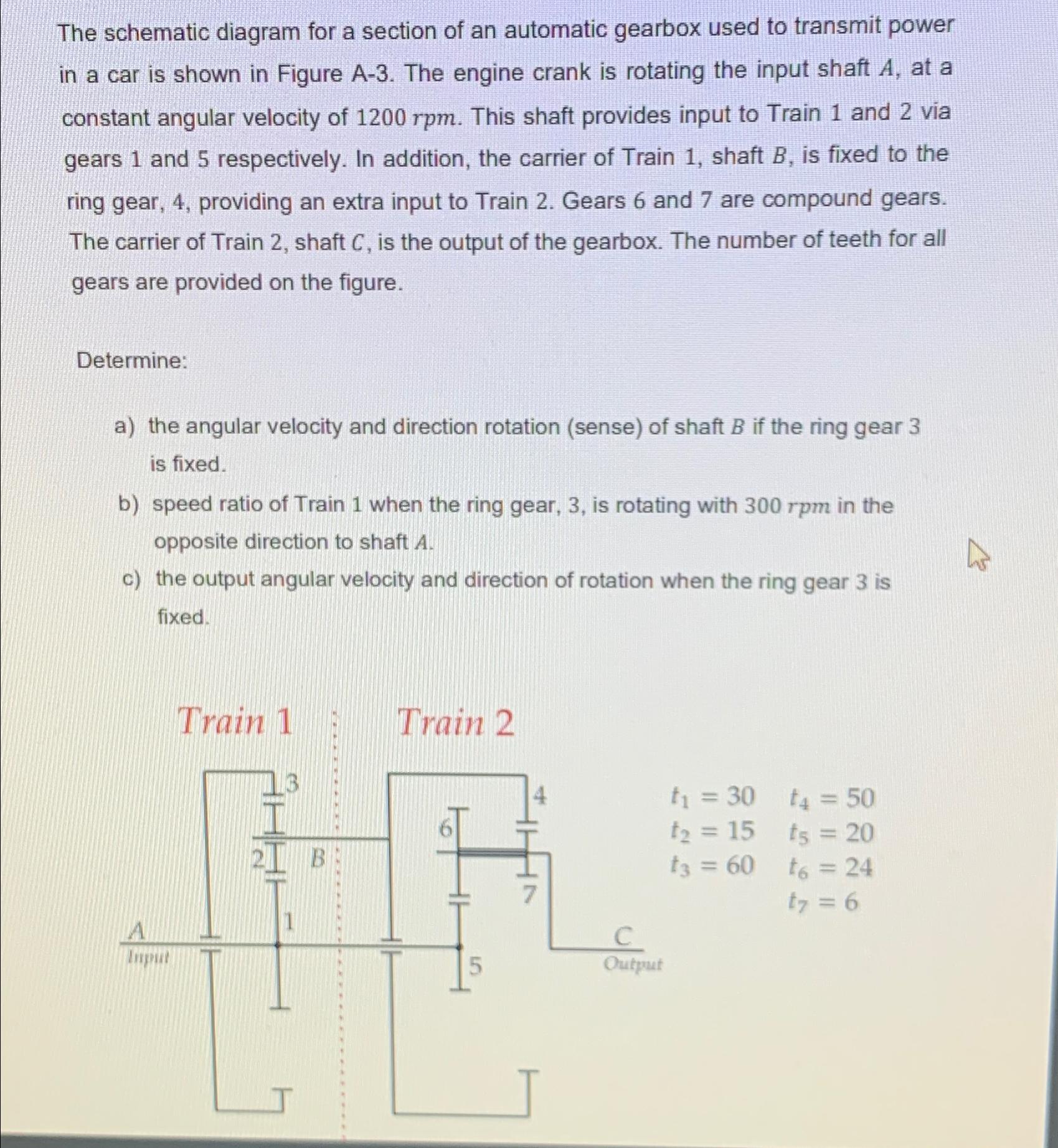
The schematic diagram for a section of an automatic gearbox used to transmit power in a car is shown in Figure A-3. The engine

The schematic diagram for a section of an automatic gearbox used to transmit power in a car is shown in Figure A-3. The engine crank is rotating the input shaft A, at a constant angular velocity of 1200 rpm. This shaft provides input to Train 1 and 2 via gears 1 and 5 respectively. In addition, the carrier of Train 1, shaft B, is fixed to the ring gear, 4, providing an extra input to Train 2. Gears 6 and 7 are compound gears. The carrier of Train 2, shaft C, is the output of the gearbox. The number of teeth for all gears are provided on the figure. Determine: a) the angular velocity and direction rotation (sense) of shaft B if the ring gear 3 is fixed. b) speed ratio of Train 1 when the ring gear, 3, is rotating with 300 rpm in the opposite direction to shaft A. c) the output angular velocity and direction of rotation when the ring gear 3 is fixed. A Input Train 1 1 Train 2 5 4 Output t = 30 t = 15 t3 = 60 t = 50 ts = 20 t6 = 24 t7 = 6
Step by Step Solution
There are 3 Steps involved in it
Step: 1
Solutions Step 1 Heres how to solve the problem a Angular velocity and direction of shaft B When ring gear 3 is fixed shaft B rotates with the same an...
Get Instant Access to Expert-Tailored Solutions
See step-by-step solutions with expert insights and AI powered tools for academic success
Step: 2

Step: 3

Ace Your Homework with AI
Get the answers you need in no time with our AI-driven, step-by-step assistance
Get Started


