Question
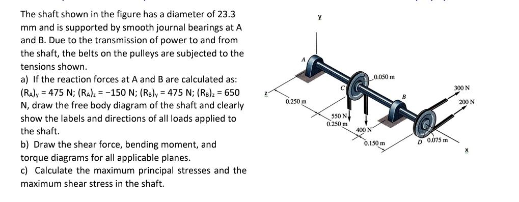
The shaft shown in the figure has a diameter of 23.3 mm and is supported by smooth journal bearings at A and B. Due

The shaft shown in the figure has a diameter of 23.3 mm and is supported by smooth journal bearings at A and B. Due to the transmission of power to and from the shaft, the belts on the pulleys are subjected to the tensions shown. a) If the reaction forces at A and B are calculated as: (RA)y 475 N; (RA)z=-150 N; (RB)y = 475 N; (RB)z = 650 N, draw the free body diagram of the shaft and clearly show the labels and directions of all loads applied to the shaft. b) Draw the shear force, bending moment, and torque diagrams for all applicable planes. c) Calculate the maximum principal stresses and the maximum shear stress in the shaft. 0.250 m Y 550 N 0.250 m 0.050 m 300 N 200 N 400 N 0.150 m D 0.075 m
Step by Step Solution
There are 3 Steps involved in it
Step: 1

Get Instant Access to Expert-Tailored Solutions
See step-by-step solutions with expert insights and AI powered tools for academic success
Step: 2

Step: 3

Ace Your Homework with AI
Get the answers you need in no time with our AI-driven, step-by-step assistance
Get StartedRecommended Textbook for
Mechanics of Materials
Authors: Russell C. Hibbeler
10th edition
134319656, 978-0134319650
Students also viewed these Mechanical Engineering questions
Question
Answered: 1 week ago
Question
Answered: 1 week ago
Question
Answered: 1 week ago
Question
Answered: 1 week ago
Question
Answered: 1 week ago
Question
Answered: 1 week ago
Question
Answered: 1 week ago
Question
Answered: 1 week ago
Question
Answered: 1 week ago
Question
Answered: 1 week ago
Question
Answered: 1 week ago
Question
Answered: 1 week ago
Question
Answered: 1 week ago
Question
Answered: 1 week ago
Question
Answered: 1 week ago
Question
Answered: 1 week ago
Question
Answered: 1 week ago
Question
Answered: 1 week ago
Question
Answered: 1 week ago
Question
Answered: 1 week ago
Question
Answered: 1 week ago
Question
Answered: 1 week ago
View Answer in SolutionInn App


