Answered step by step
Verified Expert Solution
Question
1 Approved Answer
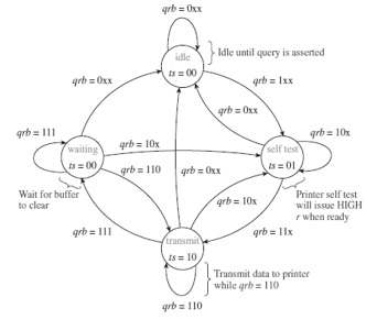
The state diagram for the ATM controller in Figure 1286 shows that when the transmission of data is complete, q goes LOW and the state
The state diagram for the ATM controller in Figure 1286 shows that when the transmission of data is complete, q goes LOW and the state transitions to idle. Make the necessary modifications to the state diagram and the VHDL program so that when q goes LOW, a transition is made to a new state called eject that sends a HIGH signal to the printer telling it to cut and eject the paper. [The FPGA now has three outputs: t, s, and e (eject)]. Build a simulation file to demonstrate its operation.

WHEN eject=> IF q = '0' THEN state
END IF;
grb 0xx Idle until query is ts00 arb 1xx grb 111 grb= 10x waitngrb 10x ts 00 self test Wait for buffer to clear Printer self test will issue HIGH r when ready grb 10x grb= 111 arb 11x transmst Transmit data to printer while qrb- 110 grb- 110 grb 0xx Idle until query is ts00 arb 1xx grb 111 grb= 10x waitngrb 10x ts 00 self test Wait for buffer to clear Printer self test will issue HIGH r when ready grb 10x grb= 111 arb 11x transmst Transmit data to printer while qrb- 110 grb- 110Step by Step Solution
There are 3 Steps involved in it
Step: 1

Get Instant Access to Expert-Tailored Solutions
See step-by-step solutions with expert insights and AI powered tools for academic success
Step: 2

Step: 3

Ace Your Homework with AI
Get the answers you need in no time with our AI-driven, step-by-step assistance
Get Started


