Answered step by step
Verified Expert Solution
Question
1 Approved Answer
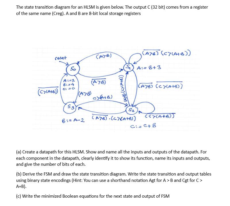
The state transition diagram for an HLSM is given below. The output C (32 bit) comes from a register of the same name (Creg).

The state transition diagram for an HLSM is given below. The output C (32 bit) comes from a register of the same name (Creg). A and B are 8-bit local storage registers reset (C>(A+B)) So A:=2 6:=4 6: = 0 S3 (A7B) B:= A-2 (A76) (A76) a>(A+B) ((())() (S) A:= B+3 S2 (A7B) (Cy(A+B)) (A76) (47(A+B)) (A7B) (CY(A+B)) (CY(A+B)) C:= C+ B (a) Create a datapath for this HLSM. Show and name all the inputs and outputs of the datapath. For each component in the datapath, clearly identify it to show its function, name its inputs and outputs, and give the number of bits of each. (b) Derive the FSM and draw the state transition diagram. Write the state transition and output tables using binary state encodings (Hint: You can use a shorthand notation Agt for A > B and Cgt for C> A+B). (c) Write the minimized Boolean equations for the next state and output of FSM
Step by Step Solution
There are 3 Steps involved in it
Step: 1
a Datapath Creation Identify Components RegistersA 8 bitsB 8 bitsCreg 32 bits Arithmetic unitsAdder 8 bits for ABComparators ABCAB Connect Components Connect registers to ALUs and comparators as per t...
Get Instant Access to Expert-Tailored Solutions
See step-by-step solutions with expert insights and AI powered tools for academic success
Step: 2

Step: 3

Ace Your Homework with AI
Get the answers you need in no time with our AI-driven, step-by-step assistance
Get Started


