Question
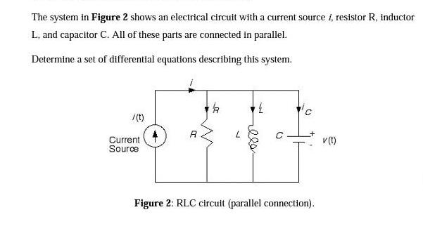
The system in Figure 2 shows an electrical circuit with a current source 1, resistor R, inductor L, and capacitor C. All of these

The system in Figure 2 shows an electrical circuit with a current source 1, resistor R, inductor L, and capacitor C. All of these parts are connected in parallel. Determine a set of differential equations describing this system. /(t) Current Source 4 A illa 7 Figure 2: RLC circuit (parallel connection). v (t)
Step by Step Solution
3.40 Rating (144 Votes )
There are 3 Steps involved in it
Step: 1
6 Now Now Now for By Kirchhoffs Law of Current i ...
Get Instant Access to Expert-Tailored Solutions
See step-by-step solutions with expert insights and AI powered tools for academic success
Step: 2

Step: 3

Ace Your Homework with AI
Get the answers you need in no time with our AI-driven, step-by-step assistance
Get StartedRecommended Textbook for
Fundamentals of Ethics for Scientists and Engineers
Authors: Edmund G. Seebauer, Robert L. Barry
1st Edition
9780195698480, 195134885, 195698487, 978-0195134889
Students also viewed these Accounting questions
Question
Answered: 1 week ago
Question
Answered: 1 week ago
Question
Answered: 1 week ago
Question
Answered: 1 week ago
Question
Answered: 1 week ago
Question
Answered: 1 week ago
Question
Answered: 1 week ago
Question
Answered: 1 week ago
Question
Answered: 1 week ago
Question
Answered: 1 week ago
Question
Answered: 1 week ago
Question
Answered: 1 week ago
Question
Answered: 1 week ago
Question
Answered: 1 week ago
Question
Answered: 1 week ago
Question
Answered: 1 week ago
Question
Answered: 1 week ago
Question
Answered: 1 week ago
Question
Answered: 1 week ago
Question
Answered: 1 week ago
Question
Answered: 1 week ago
View Answer in SolutionInn App


