Answered step by step
Verified Expert Solution
Question
1 Approved Answer
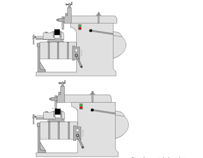
The task in this design project is to design an actuation system to power the ram's reciprocating motion in a small-size shaper. The power


The task in this design project is to design an actuation system to power the ram's reciprocating motion in a small-size shaper. The power source of the actuation system is an AC motor with 0.75 hp power rating and a maximum rotation speed of 1725 rpm (McMaster-Carr part number 5990K73). The desired ram motion, as determined by the nature of the load, is a low-speed reciprocating motion at a frequency of up to 1 Hz. To simplify the kinematic analysis, assume that the motor operates at up to 90% of the maximum power and speed in its daily operation. Also, a fast-return feature is desired to improve the operational efficiency by quickly returning the ram to its initial position after the low-speed cutting stroke. DESIGN GOALS To obtain the desired functions, the actuation system consists of two assemblies connected in series: 1) Gear Reduction Assembly. Electrical motor is a typical high-speed, low-torque power source, which needs to be coupled with a gear-reduction transmission system to boost its torque capacity. A two-stage transmission is required due to the large angular velocity ratio. The first stage should be a V-belt drive to reduce shock loading to the electric motor, and the second stage should be a gear set to transmit large torque with a relatively compact system. The transmission system is required to transmit the desired power with all safety factors no less than 2.0, and the reliability of each bearing in the transmission should exceed 99% for an expected life of 3 years (300 days per year with 8 hours' operation per day). Any components covered in ME 450 and ME 350 can be used in the design. If commercial components are used, your design must be able to demonstrate that these components meet the performance and safety factor requirements. Note that no commercial assembly can be used. For example, you can use individual off-the-shelf gears, but not gear sets. 2) Linkage System. The rotational motion after gear reduction needs to be converted into reciprocating linear translation. A linkage system with quick-return feature is required for this purpose. Scale the linkage to obtain a stroke length of 8 inches. The time ratio should be as close to 1.25 as possible. Conduct linkage synthesis to obtain the design parameters, and conduct position and velocity analyses to demonstrate that these design goals are obtained. After the linkage synthesis is completed, the corresponding position and velocity analyses should be conducted. For the position analysis, pick at least 36 points evenly distributed in a full revolution of the input shaft, and find the corresponding ram positions. The purpose is to show how the ram moves in response to the input motion. For the velocity analysis, assume a constant input speed, and find the ram velocities at various positions of the input shaft. You can use the same set of input shaft positions as in the position analysis.
Step by Step Solution
There are 3 Steps involved in it
Step: 1

Get Instant Access to Expert-Tailored Solutions
See step-by-step solutions with expert insights and AI powered tools for academic success
Step: 2

Step: 3

Ace Your Homework with AI
Get the answers you need in no time with our AI-driven, step-by-step assistance
Get Started


